Body implantable lead including one or more conductive polymer electrodes and methods for fabricating same

a technology of conductive polymer and implantable leads, which is applied in the field of body implantable, transvenous leads having one or more conductive polymer electrodes, can solve the problems of affecting interpretation, posing potentially serious risks to patients, and unable to provide sufficient charge/current to effectively and reliably terminate defibrillation

Inactive Publication Date: 2006-02-14
PACESETTER INC
View PDF37 Cites 700 Cited by
  • Summary
  • Abstract
  • Description
  • Claims
  • Application Information

AI Technical Summary

Benefits of technology

[0012]In accordance with one, specific, exemplary embodiment of the invention, there is provided an implantable lead comprising a lead body having a proximal end portion and a distal end portion. The lead body includes a conductive polymer electrode disposed along the distal end portion of the lead body for performing one or more of the functions consisting of pacing

Problems solved by technology

Both of these conditions pose potentially serious risks to the patient.
Further, at least a part of the indifferent electrode is located outside the heart so as to prevent cardiac signals from being detected by the indifferent electrode since this would interfere with the interpretation of signals sensed by the tip electrode.
The conductor supplying electrical current to the conductive polymer sleeve appears to be attached to the sleeve at a confined junction or attachment point and it is doubtful that such an arrangement can provide sufficient charge/curr

Method used


Image

  • Body implantable lead including one or more conductive polymer electrodes and methods for fabricating same
  • Body implantable lead including one or more conductive polymer electrodes and methods for fabricating same
  • Body implantable lead including one or more conductive polymer electrodes and methods for fabricating same

Examples


first embodiment

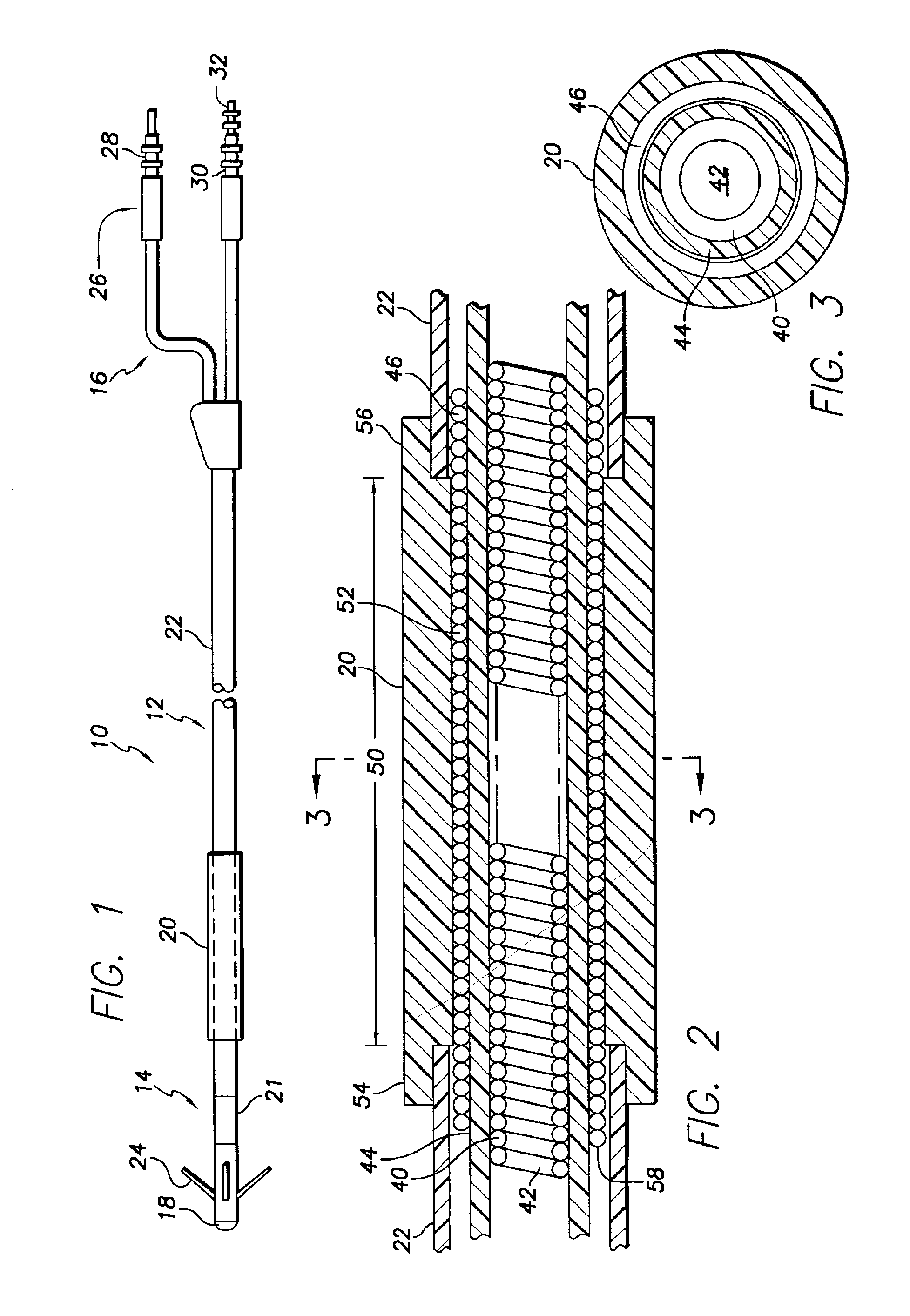
[0057]FIG. 1 shows in simplified, schematic form a passive-fixation endocardial, body implantable lead 10 in accordance with the invention. The lead 10 includes a lead body 12 having a distal end portion 14 and a proximal end portion 16. The distal end portion 14 includes a tip electrode 18 and a conductive polymer cardioversion / defibrillating shocking electrode 20, hereinafter sometimes referred to simply as a defibrillating electrode. By way of example and not limitation, the distal end portion 14 of the lead body 12 may have a diameter of about 0.026 inch (2F) to about 0.131 inch (10F), with a diameter of about 0.079 (6F) being preferred, and the electrode 20 may have a diameter of about 0.091 inch (7F) and a length of about 2 inches. As is well known in the art, a lead of the type shown may further include a sensing electrode 21 in the form of a ring positioned proximally of the tip electrode. Such a ring sensing electrode may have a length of, for example, about 0.100 inch. The...

second embodiment

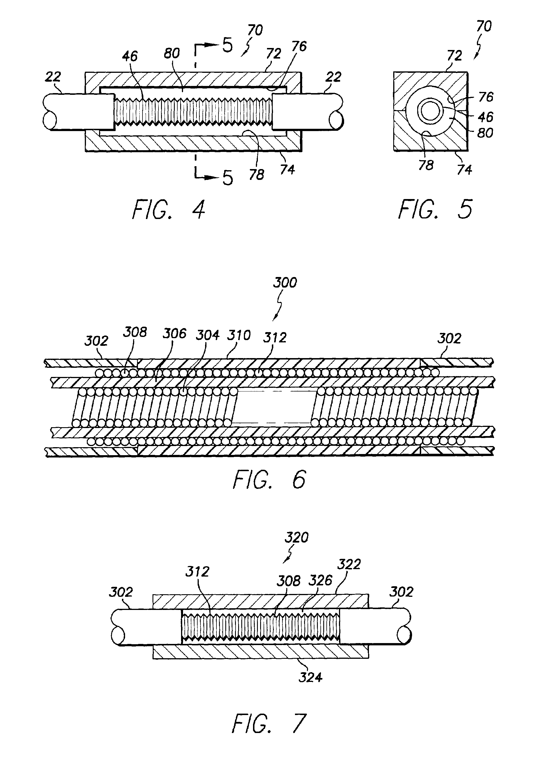
[0067]FIG. 7 shows a compression mold 320 for forming in situ, the conductive polymer defibrillating electrode 310. The mold 320 is identical to the mold shown in FIGS. 4 and 5, including two mold parts 322 and 324 together defining an internal cylindrical cavity 326 within which the conductive polymer electrode 310 is formed. Pursuant to the invention, the cylindrical cavity 326 has a diameter equal to that of the tubular housing 302.

[0068]FIGS. 8 and 9 show a portion of a body implantable endocardial lead assembly 90 in accordance with a third embodiment of the present invention. As in the first embodiment, the lead assembly 90 is adapted to transmit electrical signals between a proximal end portion (not shown) and a distal end portion a part 92 of which is shown in FIG. 8. As before, the distal end portion includes a distal extremity including a tip electrode (not shown) adapted to engage cardiac tissue and to electrically stimulate that tissue and / or sense electrical stimuli the...

fifth embodiment

[0075]As in the case of the embodiment of FIG. 6, the trilumen lead body embodiment of FIGS. 8-11 may be provided with a conductive polymer defibrillating electrode that has the same outer diameter as that of the lead housing. In this connection, FIGS. 13 and 14 show the invention comprising a lead body 370 including a trilumen housing 372 having a window 374 for exposing uninsulated lengths of one or more cable conductors 376 about which a conductive polymer electrode 378 is molded. To achieve the isodiametric structure desired, the outer diameter of the housing 372 is reduced at 380, that is, along the window 374. As before, a 2-part compression mold 382 (FIGS. 15 and 16) is preferably used to fabricate the conductive polymer electrode 378.

[0076]FIGS. 8-16 illustrate leads in accordance with the present invention that in each case comprises a multilumen housing including a pair of redundant cables (or small diameter, finely wound coils) electrically connecting a conductive polymer...


PUM


Abstract

A body implantable lead comprises a lead body including a conductive polymer electrode disposed along a distal end portion of the lead body for performing one or more of the functions consisting of pacing, sensing, cardioversion and defibrillation. An electrical conductor, preferably in the form of a multistrand cable conductor, couples the conductive polymer electrode with a proximal end of the lead body. The conductive polymer electrode encapsulates the conductor and is in electrical contact therewith along the length, and preferably along substantially the entire length, of the conductive polymer electrode. The lead body may comprise a multilumen polymer housing, the conductor being contained within one of the lumens of the housing. The conductive polymer electrode may be disposed within a window formed in the lead body. Alternatively, the conductive polymer electrode may comprise multiple electrode sections within a corresponding number of windows formed in the lead body and spaced apart along the length thereof. Further, the window and the conductive polymer electrode disposed therein may extend helically about the lead body. Because of its flexibility and because it can have a small diameter, the lead of the invention is particularly advantageous for implantation in the small, tortuous vessels of the coronary sinus region of the heart for left side stimulation and/or sensing.
Methods of fabricating lead bodies incorporating conductive polymer electrodes are also disclosed.

Description

FIELD OF THE INVENTION[0001]The present invention relates generally to body implantable leads. More particularly, the invention relates to body implantable, transvenous leads having one or more conductive polymer electrodes. The invention further relates to methods for fabricating such leads.BACKGROUND OF THE INVENTION[0002]Body implantable, transvenous leads form the electrical connection between a pulse generator such as a cardiac pacemaker and / or ICD and the heart tissue which is to be stimulated. The leads include a lead body comprising a tubular, flexible biocompatible, biostable insulative sheath or housing of silicone rubber, polyurethane or other suitable polymer. In a typical bipolar lead having a tip electrode and a ring sensing electrode, two coaxial coil conductors with insulation in between are carried within the insulative housing. One of the coil conductors connects the pulse generator with the tip electrode while the other coil conductor, somewhat shorter than the fi...

Claims


Application Information

Patent Timeline
IPC IPC(8): A61N1/05
CPCA61N1/056A61N1/0563A61N2001/0585
Inventor JENNEY, CHRISTOPHER R.WILLIAMS, SHELDON
Owner PACESETTER INC
Why Eureka
Try Eureka