
Method of repairing a crack in a component utilizing friction stir welding

a technology of friction stir welding and component, applied in the field of aircraft component crack repair, can solve the problems of increasing the number of cracks to develop, increasing the growth of existing cracks in aircraft components, and increasing the cost of crack repair in military and commercial aircra

Inactive Publication Date: 2006-02-21
THE BOEING CO
View PDF10 Cites 20 Cited by
  • Summary
  • Abstract
  • Description
  • Claims
  • Application Information

AI Technical Summary

Benefits of technology

[0011]The present invention has several advantages over existing crack repairing techniques. One advantage of the present invention is that it provides a welding process of repairing cracks that does not melt material of the component, thereby, providing minimal distortion, residual stress, and alteration to chemical and physical properties of the component.
[0012]Another advantage of the present invention is that it provides a method of fusing materials surrounding a crack that traditionally are known to be unweldable.
[0013]Furthermore, the present invention provides a method of repairing a crack that is more durable and longer lasting than traditional repair techniques.

Problems solved by technology

Increased fatigue has caused an increasing number of cracks to develop and an increased amount of growth of existing cracks in aircraft components.
Crack initiation and growth is also a concern due to potential inability to operate the aircraft, time and costs involved in repair of the cracks, and reoccurrence of crack growth after repair.
Repair of cracks in both military and commercial aircraft is costly and generally crack repair is only a temporary solution.
Stop drilling is only a temporary fix, typically the cracks over time return to growing, since area surrounding the crack is fatigued and the additional holes further weaken the component.
The metallic patch is fastened to the component of interest, also forming a bond with the component, via multiple fasteners such as rivets or bolts, which is labor intensive.
Although, the repairing methods are more durable and hold up for a longer period of time than the stop drilling method, they too are only temporary.
Thus, none of the above-described methods fully repair or eliminate cracks and eventually the cracks return to growing.

Method used


Image

  • Method of repairing a crack in a component utilizing friction stir welding
  • Method of repairing a crack in a component utilizing friction stir welding
  • Method of repairing a crack in a component utilizing friction stir welding

Examples


Embodiment Construction

[0025]While the present invention is described with respect to a method of repairing a crack of a component of an aircraft, the present invention may be adapted for various applications including: aeronautical vehicles, land-based vehicles, nautical vehicles, or other applications known in the art that require repair of a crack.

[0026]In the following description, various operating parameters and components are described for one constructed embodiment. These specific parameters and components are included as examples and are not meant to be limiting.

[0027]Also, in the following description the term “component” refers to any vehicle component including a panel, a stiffner, a longeron, a rib, or other vehicle component known in the art. The component may be formed of aluminum, magnesium, steel, copper, titanium, or a nickel based alloy such as inconel. The aluminum may be of various series type known in the art such as 2000, 5000, 6000, 7000, and 8000 series aluminum. The component may...


PUM

PropertyMeasurementUnit
areaaaaaaaaaaa
metallicaaaaaaaaaa
adhesiveaaaaaaaaaa

Abstract

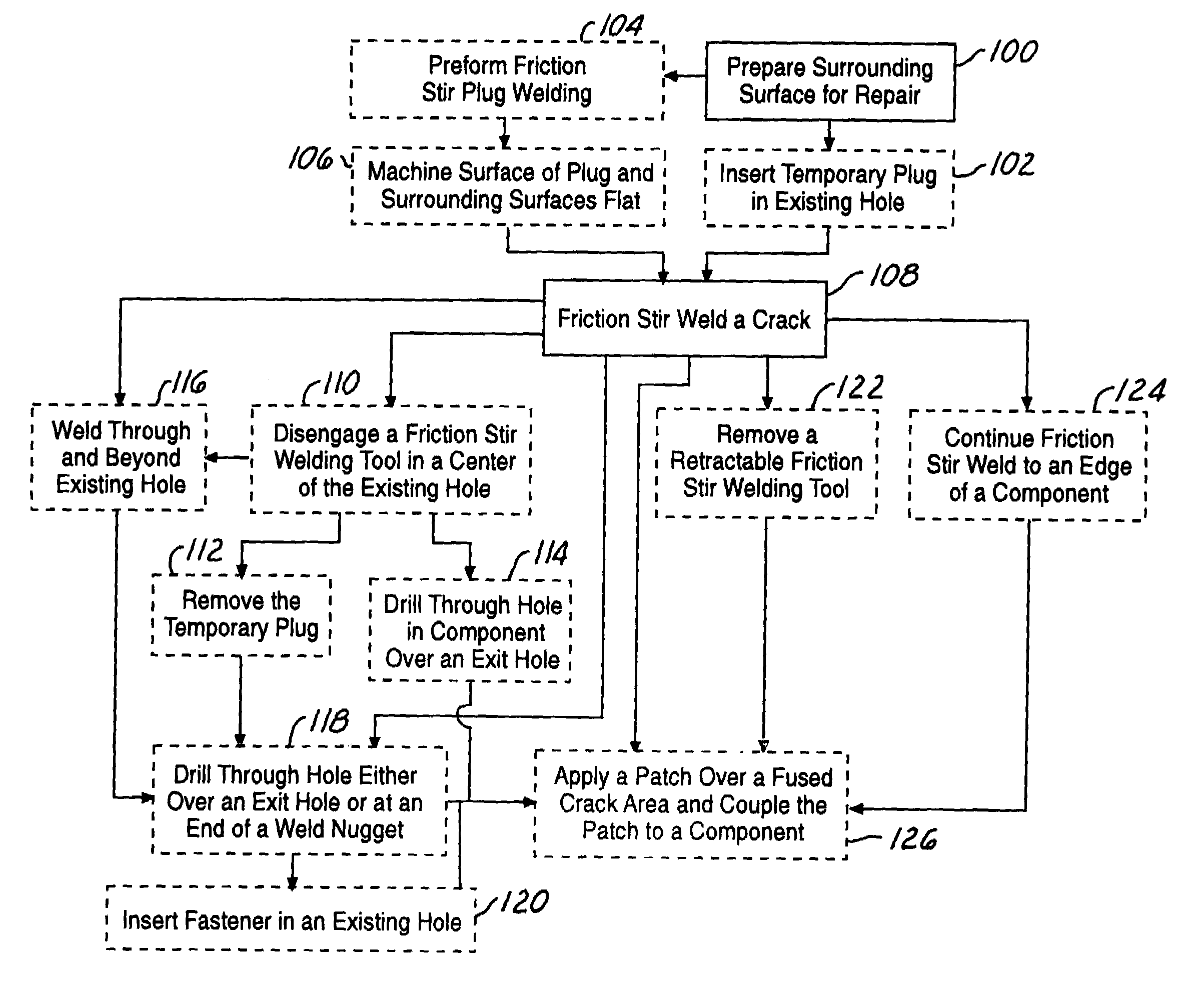
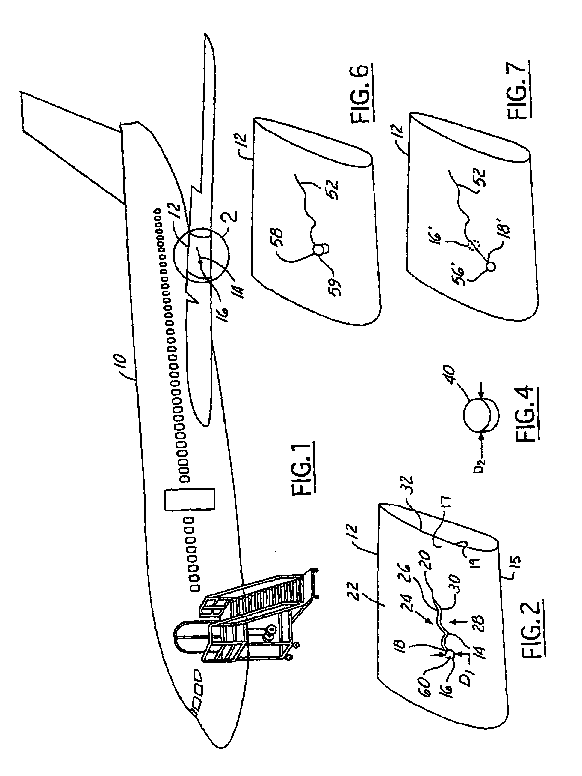
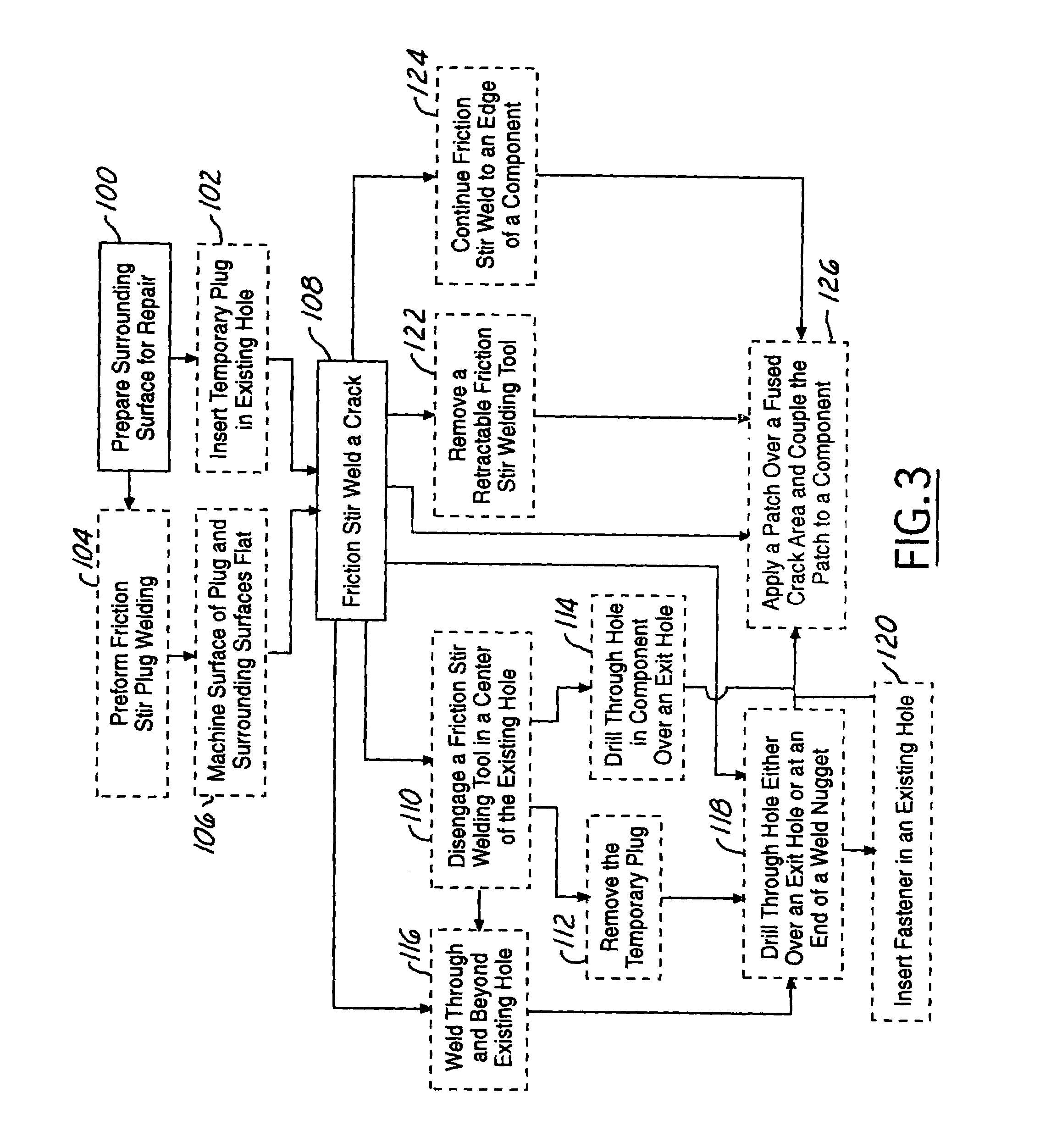
A method of repairing a crack (14) in a component (12). The method includes preparing a surrounding surface (22) of the crack (14) for repair and welding a first portion (24) of the component (12) on a first side (26) of the crack (14) to a second portion (28) of the component (12) on a second side (30) of the crack (14) to form a fused crack area (50). The method may also include applying a patch (78) over the fused crack area (50) for additional strength.

Description

RELATED APPLICATION[0001]The present invention is related to U.S. Pat. No. 5,697,544 entitled “ADJUSTABLE PIN FOR FRICTION STIR WELDING TOOL” incorporated by reference herein.TECHNICAL FIELD[0002]The present invention relates generally to aeronautical vehicle systems, and more particularly, to a method of repairing a crack in an aircraft component.BACKGROUND OF THE INVENTION[0003]Service life of an aircraft is currently longer than in previous years and it is foreseeable and expected that service life will continue to increase in the future. The service life for many aircraft is longer and thus components of the aircraft are being utilized, in operation of the aircraft, for longer periods of time than originally intended and designed.[0004]Due to the longer operating lives of the aircraft components, concerns have been expressed relating to fatigue life of the components. In particular, crack initiation, crack growth, and related topics have become of interest. Increased fatigue has...

Claims


Application Information

Patent Timeline
Patent Type & Authority Patents(United States)
IPC IPC(8): B23P6/00B23K20/12B23P6/04B64F5/00
CPCB23K20/122B23P6/00B23P6/04B64F5/0081B23K20/1295Y10T29/49723B23P2700/01Y10T29/49718Y10T29/49734Y10T29/49739Y10T29/49735Y10T29/49728Y10T29/49732Y10T29/49746Y10T29/49742B64F5/40B23K20/12
Inventor TALWAR, RAJESHPEREZ, RIGOBERTO
Owner THE BOEING CO
Learn More