
Controller of cylinder injection type internal combustion engine

a technology of internal combustion engine and control system, which is applied in the direction of electric control, machines/engines, output power, etc., can solve the problems of large amount of internal egr gas, large amount of hc is exhausted from the combustion chamber, and large amount of hc is exhausted

Inactive Publication Date: 2006-02-21
HITACHI LTD
View PDF9 Cites 49 Cited by
  • Summary
  • Abstract
  • Description
  • Claims
  • Application Information

AI Technical Summary

Benefits of technology

[0008]An object of the present invention is to provide a control device for an direct injection internal combustion engine, which can effectively reduce the amounts of HC and NOx exhausted from a combustion chamber during a period from the start of the engine operation to the stop of the engine operation.
[0010]With the construction set forth above, the amounts of both HC and NOx exhausted from a combustion chamber during a period from the start of the engine operation to the stop of the engine operation can effectively be reduced.

Problems solved by technology

Accordingly, if the EGR gas is returned in an excessive amount, a problem arises in that a large amount of HC is exhausted from the combustion chamber and combustion becomes instable.
Also, a large amount of internal EGR gas is required to effectively reduce the amount of NOx exhausted from the combustion chamber by using the internal EGR gas.
However, if a variable valve is controlled to increase the amount of internal EGR gas, there arises a problem in instability of combustion or a lowering of engine torque.
Further, if the engine undergoes stratified charge combustion in a cold state, another problem occurs in that injected fuel is attached to the wall surfaces of the combustion chamber and a large amount of HC is exhausted.

Method used


Image

  • Controller of cylinder injection type internal combustion engine
  • Controller of cylinder injection type internal combustion engine
  • Controller of cylinder injection type internal combustion engine

Examples


Embodiment Construction

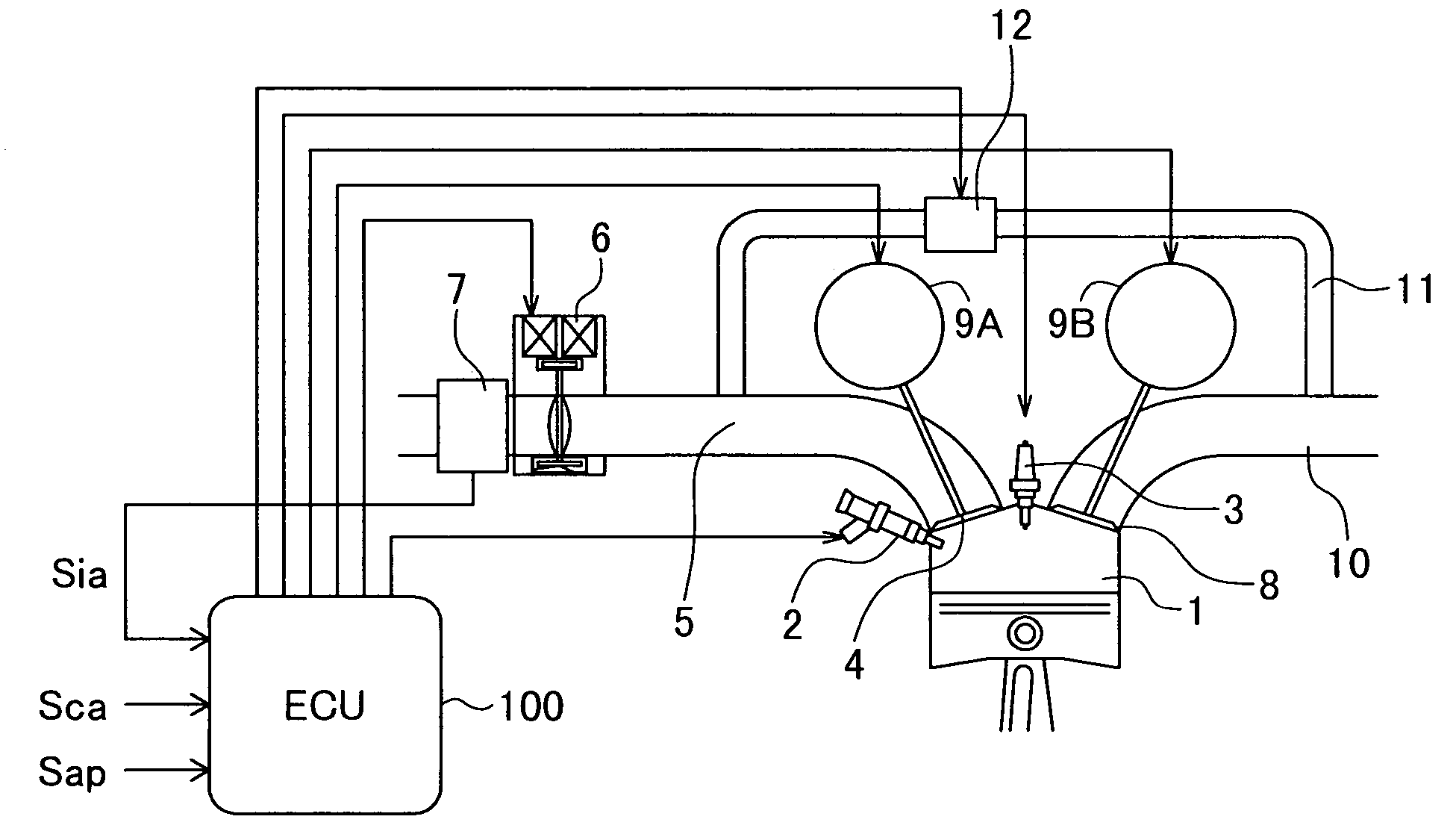
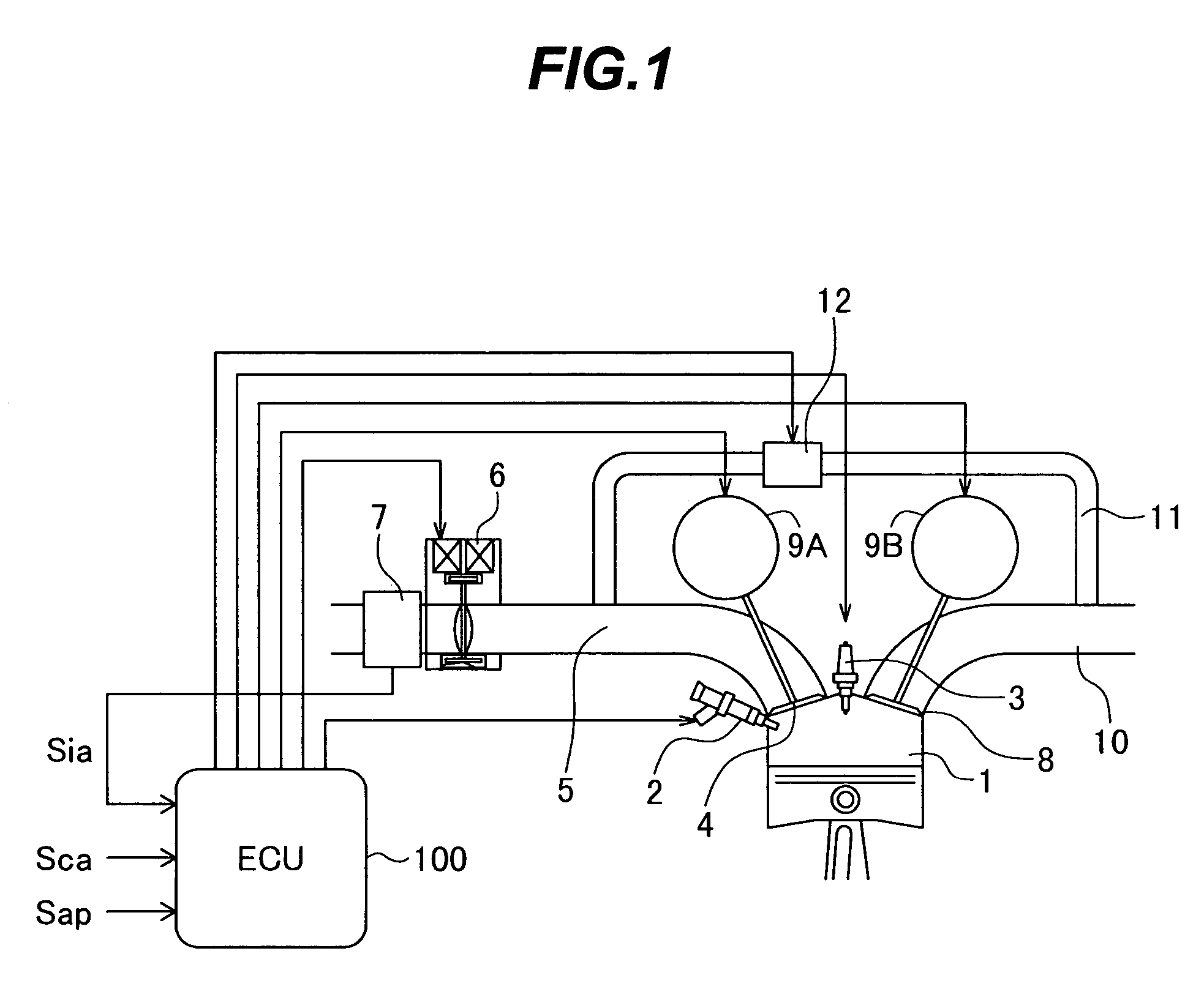
[0033]The construction and operation of a control system for an direct injection internal combustion engine according to one embodiment of the present invention will be described below with reference to FIGS. 1 to 17.

[0034]The overall construction of the direct injection internal combustion engine according to this embodiment of the present invention will first be described with reference to FIG. 1.

[0035]FIG. 1 is an overall schematic view of the direct injection internal combustion engine according to the one embodiment of the present invention.

[0036]The direct injection internal combustion engine according to this embodiment includes a fuel injection valve 2 disposed on one side of a combustion chamber 1, and an ignition plug 3 disposed centrally on an upper surface of the combustion chamber 1. The fuel injection valve 2 is able to inject fuel to the combustion chamber 1 at free timing regardless of the operation of an intake valve 4.

[0037]In stratified charge combustion that is a...


PUM


Abstract

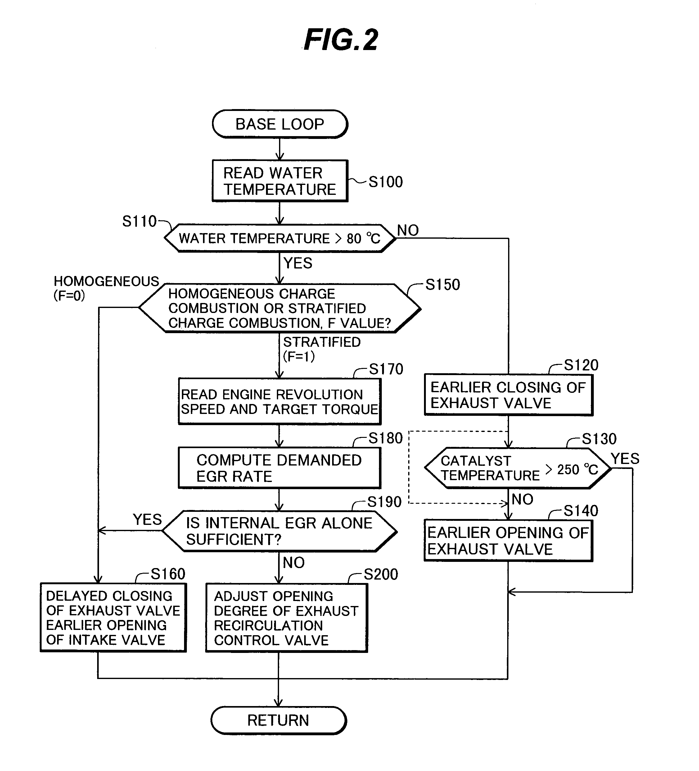
The present invention is intended to provide a control system for an direct injection internal combustion engine capable of effectively reducing the amounts of both HC and NOx exhausted from a combustion chamber during a period from the start of the engine operation to the stop of the engine operation. It comprises an external EGR passage (11) for returning a part of exhaust gas from an exhaust pipe (10) to an intake pipe (5), an external EGR control valve (12) for controlling an amount of exhaust gas returned to the external EGR passage (11), and a valve timing varying mechanism (9A, 9B) for varying timing of opening and closing at least one of an intake valve and an exhaust valve. An ECU 100 controls the valve timing varying mechanism (9A, 9B) to always return internal EGR gas in an operation region where exhaust gas recirculation is required, and controls the external EGR control valve (12) to return exhaust gas in a combination of internal EGR and external EGR when an internal EGR rate provided by the valve timing varying mechanism (9A, 9B) is not sufficient to satisfy an EGR rate demanded depending on an operation state.

Description

TECHNICAL FIELD[0001]The present invention relates to a control system for an direct injection internal combustion engine, and more particularly to a control system for an direct injection internal combustion engine suitable for use in control of the direct injection internal combustion engine equipped with an exhaust gas recirculation (EGR) device.BACKGROUND ART[0002]One known control system for an direct direct injection internal combustion engine equipped with an exhaust gas recirculation device is disclosed in, e.g., JP,A 2-245460. In the known control system, only internal EGR gas is returned to a combustion chamber in a low load range, and external EGR gas is returned to the combustion chamber in a high load range.[0003]JP,A 6-323201, for example, discloses another control system for an internal combustion engine in which an air-fuel ratio is controlled so as to provide a larger air surplus rate in a low load range than in a high load range, the engine including a first EGR de...

Claims


Application Information

Patent Timeline
Patent Type & Authority Patents(United States)
IPC IPC(8): F01N3/00F02B23/10F02B31/08F02B75/12F02D13/02F02D21/08F02D41/00F02F3/26F02M25/07
CPCF02D13/0219F02D41/006F02M25/0715F02M25/0752F02D41/0065F02B23/104F02B31/085F02B2023/106F02B2075/125Y02T10/47F02D2041/001F02F3/26Y02T10/18Y02T10/123F02M26/13F02M26/01Y02T10/12Y02T10/40
Inventor TOKUYASU, NOBORUNOGI, TOSHIHARUSHIRAISHI, TAKUYA
Owner HITACHI LTD
Learn More