Exhaust emission control device of engine

a technology of exhaust emission control and control device, which is applied in the direction of electric control, machines/engines, mechanical equipment, etc., can solve the problems of inability to accurately detect the quantity of pms that are caught by the dpf, the counter is inevitably reset at once, and the pms that are deposited on the dpf may be spontaneously ignited and burned, etc., to achieve accurate setting of an interval for compulsive regeneration

Inactive Publication Date: 2006-02-21
MITSUBISHI FUSO TRUCK AND BUS CORPORATION
View PDF10 Cites 32 Cited by
  • Summary
  • Abstract
  • Description
  • Claims
  • Application Information

AI Technical Summary

Benefits of technology

[0013]The object of the present invention is to provide an exhaust emission control device and an exhaust emission control method capable of continuous regeneration of a diesel particulate filter and of accurately setting an interval for compulsive regeneration.
[0015]Thus, the interval for the start of continuous regeneration can be properly adjusted in accordance with the history of the circumstances in which a state for continuous regeneration is realized. Accordingly, the circumstances in which the continuous regeneration state is realized are reflected in the compulsive regeneration interval, so that unnecessary compulsive regeneration and retardation of the compulsive regeneration can be prevented. In consequence, the fuel-efficiency and exhaust gas performance can be improved.
[0016]Preferably, the compulsive regeneration control element adds up cases in which the parameter related to the temperature of the diesel particulate filter continues to be not lower than a given temperature for a given time, and the interval is lengthened with the increase of the resulting cumulative value. According to this configuration, the interval can be adjusted with the circumstances for the realization of the continuous regeneration state reflected in it, the fuel-efficiency and exhaust gas performance can be improved.
[0017]Preferably, the filter temperature related value detecting element detects the temperature of the exhaust gas directly on the upper-stream side of the diesel particulate filter, and the compulsive regeneration control element adjusts the interval in accordance with the exhaust gas temperature and executes the compulsive regeneration control in accordance with the exhaust gas temperature. According to this configuration, the exhaust gas temperature directly on the upper-stream side of the diesel particulate filter is used for the control for the adjustment of the compulsive regeneration interval and the compulsive regeneration control, so that both the control systems are simplified.

Problems solved by technology

It is hard accurately to detect the quantity of PMs that are caught by the DPF while a vehicle is running.
Thus, in some driving conditions of the vehicle, the PMs that are deposited on the DPF may be spontaneously ignited and burned before the aforesaid interval terminates.
According to the prior art described above, however, the counter is inevitably reset at once if a temperature of, e.g., 600° C. or more at which the DPF is brought to the regeneration state by self-burning is detected.
If the counter is reset in this manner with the DPF not fully regenerated, the start of the next cycle of compulsive regeneration is retarded, so that the exhaust gas is rendered annoying.
Since combustion at 600° C. or more advances hastily in the DPF, however, the incidence of this problem may be relatively low.
If the aforesaid method in which the counter is reset is used, therefore, the compulsive regeneration is retarded too much for practical use.

Method used


Image

  • Exhaust emission control device of engine
  • Exhaust emission control device of engine
  • Exhaust emission control device of engine

Examples


Embodiment Construction

[0022]An embodiment of the present invention will now be described with reference to FIGS. 1 to 3.

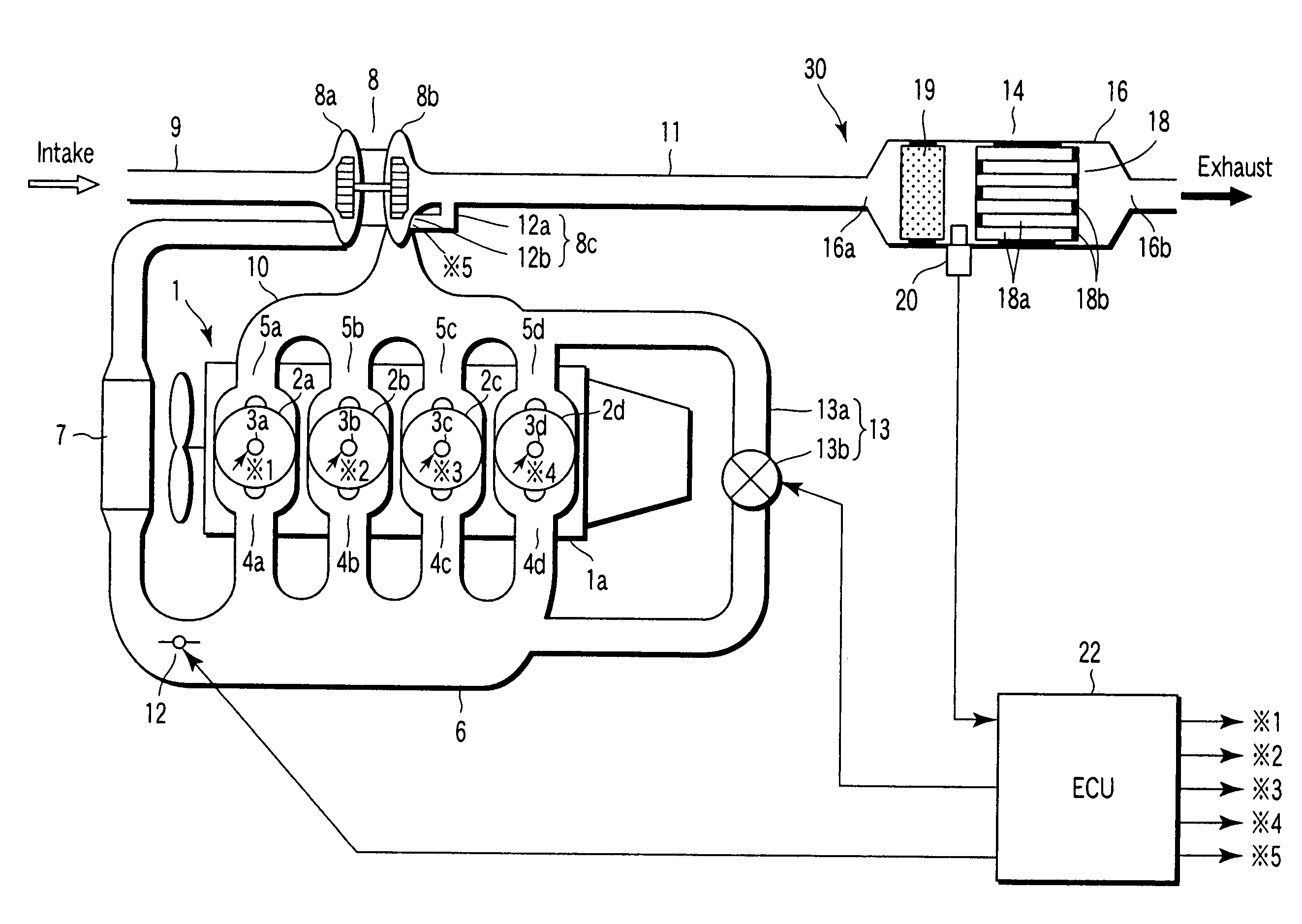
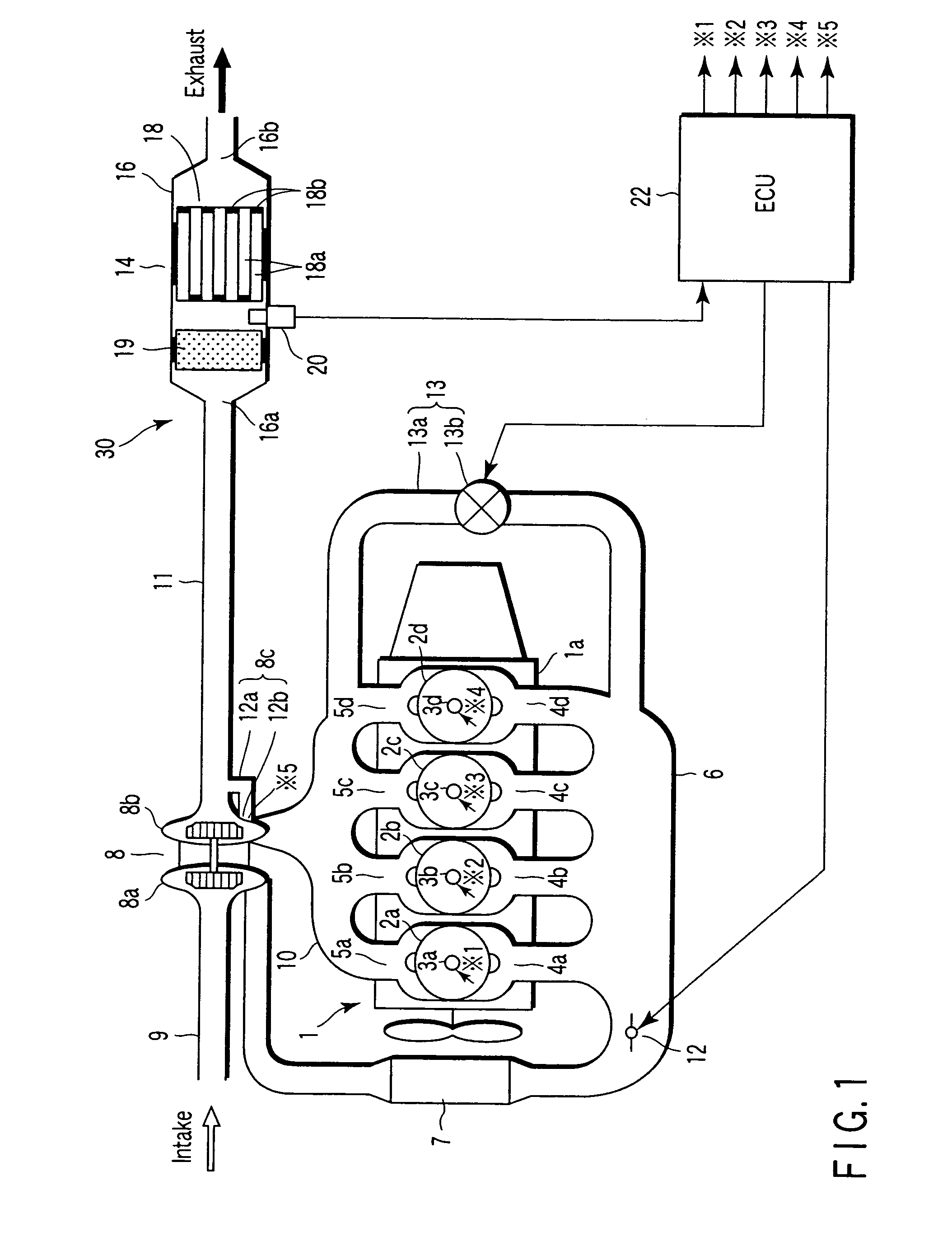
[0023]FIG. 1 shows a diesel engine 1 for run, as an example of an internal-combustion engine, which is mounted in a vehicle, such as a truck or bus. The diesel engine 1 is furnished with an exhaust emission control device 30. An engine body la of the diesel engine 1 is provided with four cylinders 2a to 2d that are arranged in series with one another, for example.

[0024]Each of the cylinders 2a to 2d holds a piston (not shown) for reciprocation. The respective top portions of cylinders 2a to 2d are provided with injectors 3a to 3d, intake ports 4a to 4d, exhaust ports 5a to 5d, and intake-exhaust valves (not shown), respectively.

[0025]Fuel suppliers (not shown) are connected to the injectors 3a to 3d, individually. Intake-exhaust operations of the intake-exhaust valves and injection operations of the injectors 3a to 3d are carried out at given points of time for the individual cylinders ...


PUM


Abstract

An exhaust emission control device comprises a temperature sensor for detecting the temperature of exhaust gas directly on the upper-stream side of a diesel particulate filter. An ECU adjusts a compulsive regeneration interval in accordance with a cumulative history of cases in which the exhaust gas temperature detected by means of the temperature sensor continues to be not lower than a value equivalent to a continuous regeneration temperature. The compulsive regeneration interval is adjusted by means of the ECU in accordance with a history of circumstances in which a state for continuous regeneration is realized.

Description

CROSS-REFERENCE TO RELATED APPLICATIONS[0001]This application is based upon and claims the benefit of priority from the prior Japanese Patent Application No. 2002-329634, filed Nov. 13, 2002, the entire contents of which are incorporated herein by reference.BACKGROUND OF THE INVENTION[0002]1. Field of the Invention[0003]The present invention relates to an exhaust emission control device of an engine and an exhaust emission control method, using a diesel particulate filter set in an exhaust passage of the engine and an oxidation catalyst located on the upper-stream side of the filter.[0004]2. Description of the Related Art[0005]A diesel particulate filter (hereinafter referred to as DPF) is used as an exhaust emission control device that is attached to a diesel engine, an example of an internal-combustion engine. The DPF is provided in the exhaust passage of the engine, and catches particulate matters (hereinafter referred to as PMs) in the exhaust gas of the engine.[0006]The DPF mus...

Claims


Application Information

Patent Timeline
Patent Type & Authority Patents(United States)
IPC IPC(8): F01N3/00F01N3/02F01N3/023F01N3/025F01N3/029F01N3/035F01N9/00F01N13/02F02B37/00F02B37/18F02D21/08F02D41/00F02D41/02F02M25/07
CPCF01N3/023F01N3/035F02B37/18F01N13/0097F02D41/029F02D41/0245F02B37/00F02D41/0007F02D41/0055F02D2200/0802F02M25/0707F02M25/0713Y02T10/144Y02T10/26F02M26/05F02M26/10Y02T10/12F01N9/00
Inventor KAGENISHI, MASAO
Owner MITSUBISHI FUSO TRUCK AND BUS CORPORATION
Why Eureka
Try Eureka