
Method for controlling fluid flow to and from an eye during ophthalmic surgery

a technology for controlling the flow of fluid to and from the eye during ophthalmic surgery, which is applied in the field of ophthalmic surgery, can solve the problems of limited irrigation control of surgeons

Inactive Publication Date: 2006-02-21
JOHNSON & JOHNSON SURGICAL VISION INC
View PDF3 Cites 11 Cited by
  • Summary
  • Abstract
  • Description
  • Claims
  • Application Information

AI Technical Summary

Benefits of technology

The present invention relates to a method and apparatus for controlling fluid flow to and from an eye during ophthalmic surgery. The technical effects of this invention include maintaining proper eye pressure, automatically regulating fluid flow rates based upon pressure determination, and providing an indication of wound leaking. The apparatus includes a supply of irrigation fluid, a positive displacement pump, a vacuum source, and a control system for adjusting fluid flow rates based upon pressure determination. The control system may also include an indication for monitoring wound construction consistency.

Problems solved by technology

In addition, the surgeon control of irrigation is limited to an on / off control valve and adjustment of the irrigation fluid source height.

Method used


Image

  • Method for controlling fluid flow to and from an eye during ophthalmic surgery
  • Method for controlling fluid flow to and from an eye during ophthalmic surgery
  • Method for controlling fluid flow to and from an eye during ophthalmic surgery

Examples


Embodiment Construction

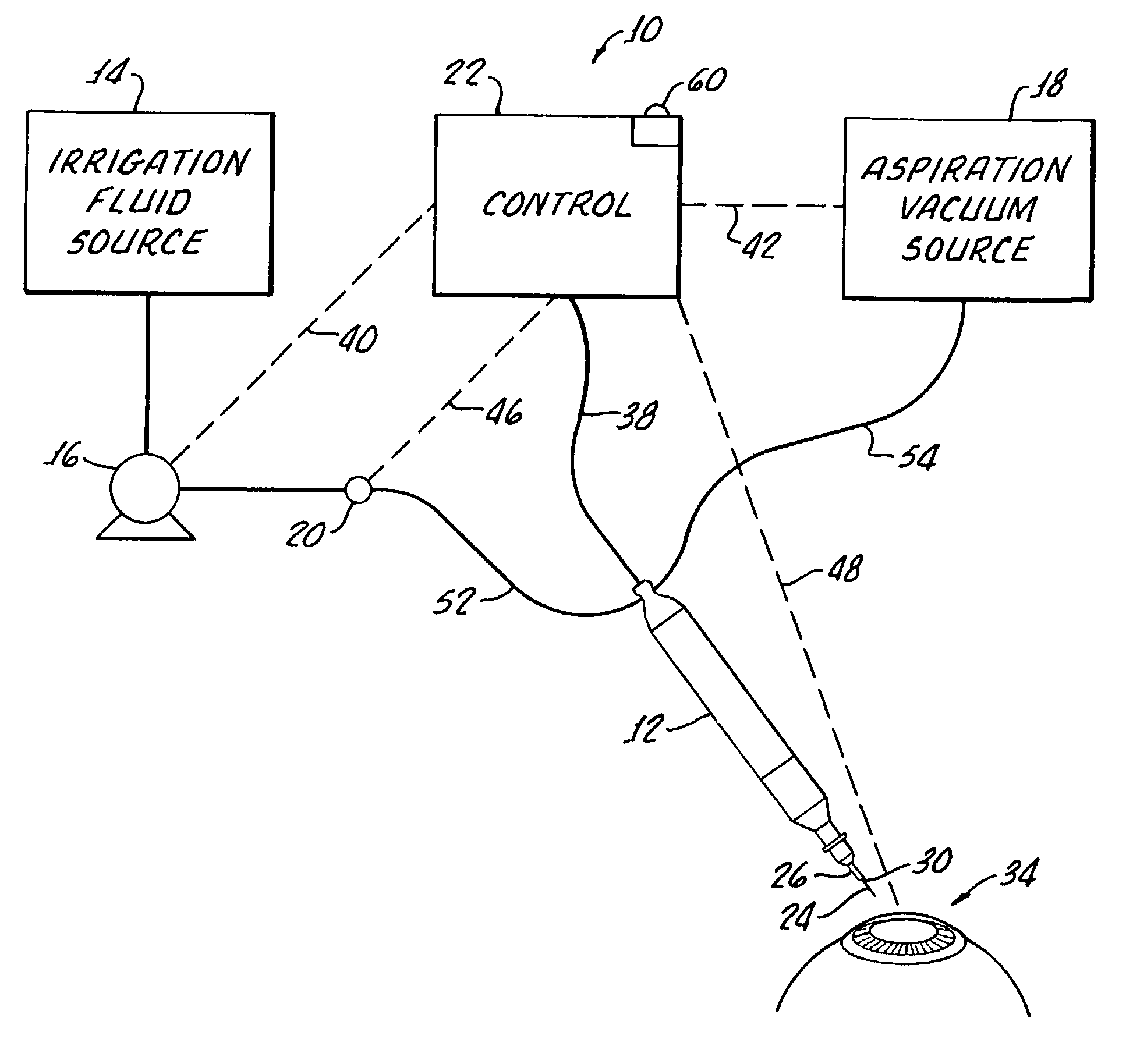
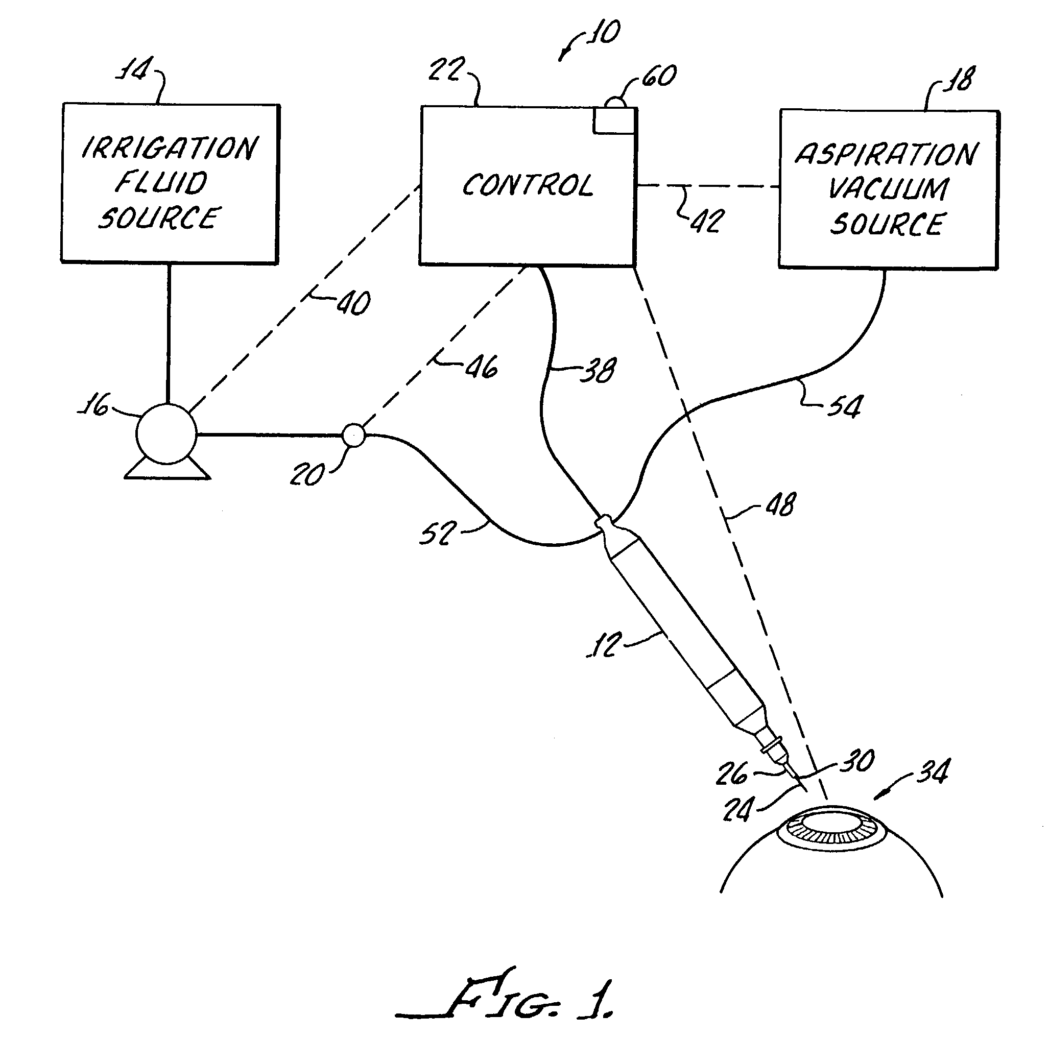
[0027]With reference to FIG. 1, there is shown apparatus 10 in accordance with the present invention for controlling fluid flow to and from a phacoemulsification handpiece 12 which generally includes a supply 14 of irrigation fluid, a positive displacement pump 16, a vacuum source 18, a pressure sensor 20 and a control system 22 described hereinafter in greater detail and also suitable for performing the method of the present invention.

[0028]It should be appreciated that while a phacoemulsification handpiece 12 is described herein for the practice of the present invention, for illustration purposes, other surgical instruments (not shown) may be utilized for different ophthalmic surgical procedures and separate infusion and aspiration needles (not shown) may be used for practice of the present invention.

[0029]The handpiece 12, which may be of any conventional type, includes an ultrasonically driven, hollow needle 24 having a sleeve 26 thereabout which establishes an annulus 30 round ...


PUM


Abstract

A method and apparatus provided for controlling fluid control to and from an eye or a phacoemulsification handpiece. The handpiece includes an ultrasonically driven, hollow, sleeved needle and the method includes inserting the needle and sleeve into an eye for phacoemulsification of eye tissue and introducing fluid into the eye through an annulus established between the sleeve and the needle. Aspiration of fragmented tissue and fluid from the eye is conducted through the hollow needle. An initial irrigation fluid pressure is determined and the irrigation fluid flow and aspiration fluid flow are adjusted based upon the initial determination. Thereafter continued determination of irrigation fluid pressure is utilized to continuously adjust irrigation fluid flow and / or aspiration fluid flow.

Description

[0001]This is a divisional of application Ser. No. 09 / 918,749, filed Jul. 31, 2001, now U.S. Pat. No. 6,579,255.[0002]The present invention generally relates to a method and apparatus for ophthalmic surgery. More specifically, the present invention is directed to a method and apparatus for controlling fluid flow to and from an eye during ophthalmic surgery.[0003]In retinal and vitreous surgery, a separate needle used to supply infusion, or irrigation, fluid or suction, for aspiration, respectively.[0004]Phacoemulsification procedures typically include the use of a handpiece for inserting a sleeved needle through a corneal incision and thereafter vibrating the needle in order to emulsify hard nuclear material of the cataract lens. The incision is generally made in the region of the limbus or in the cornea.[0005]An annulus formed between the sleeve and the needle functions as a passage which allows for the introduction, or inflow, of the saline fluid into the eye for irrigation.[0006]...

Claims


Application Information

Patent Timeline
Patent Type & Authority Patents(United States)
IPC IPC(8): A61M1/00A61F9/007
CPCA61F9/00745A61M1/0084A61M1/85
Inventor KADZIAUSKAS, KENNETH E.COLE, MARK S.
Owner JOHNSON & JOHNSON SURGICAL VISION INC
Learn More