Ultra-high pressure discharge lamp
Active Publication Date: 2006-02-21
USHIO DENKI KK
View PDF6 Cites 2 Cited by
- Summary
- Abstract
- Description
- Claims
- Application Information
AI Technical Summary
Benefits of technology
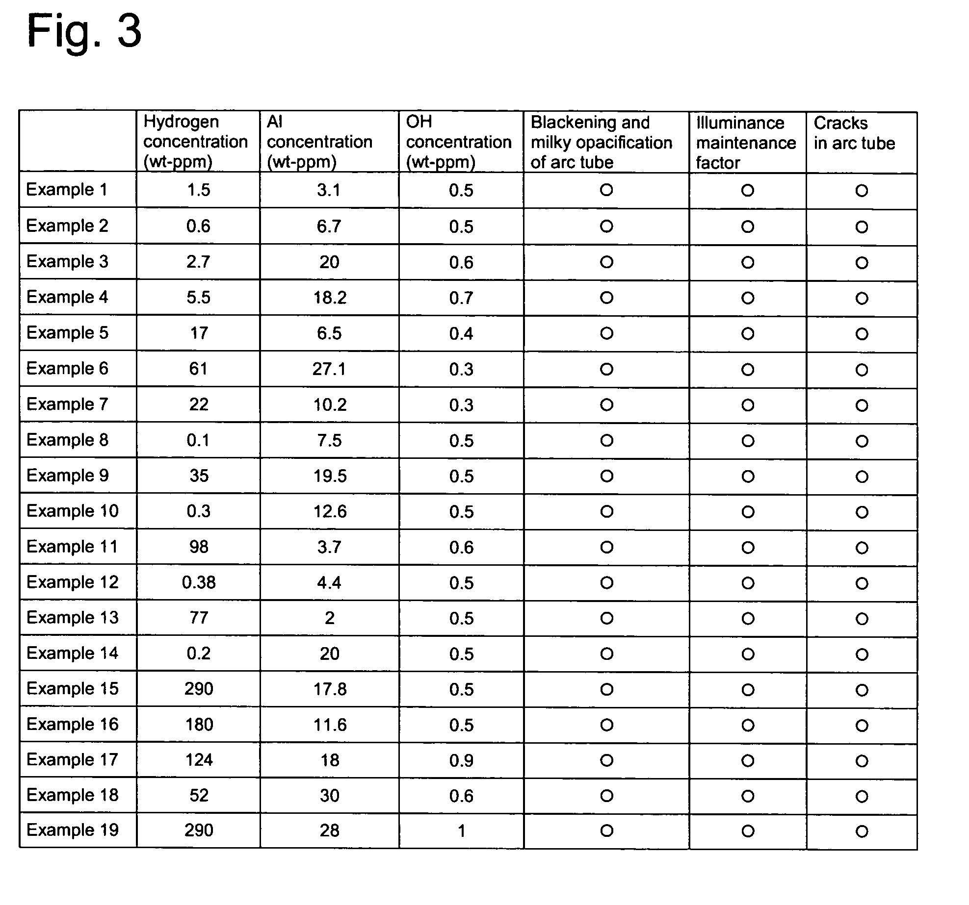
[0056]Here, ultra-high pressure discharge lamps which were produced for carrying out a test with respect to the action and the effect of the invention are described.
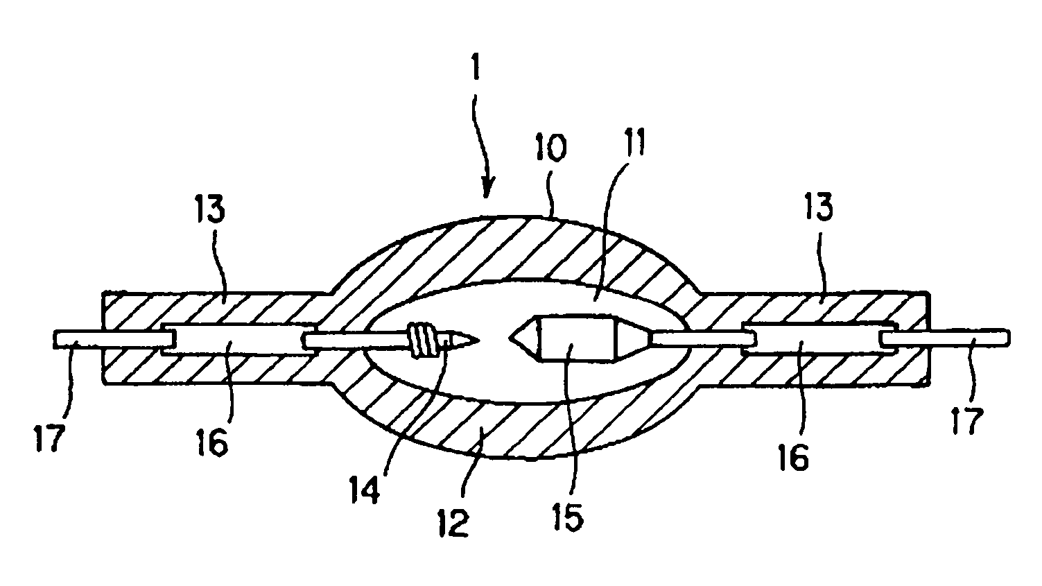
[0057]The hydrogen concentration in the silica glass, the concentration of OH radicals and the aluminum concentration is fixed within the range of numerical values of the invention. Nineteen ultra-high pressure discharge lamps with the arrangement shown in FIG. 1 were produced using the following specification.(Ultra-high Pressure Discharge Lamp)
[0058]maximum outside diameter of the arc tube part: 11 mm
[0066]The hydrogen concentration in the silica glass, the concentration of OH radicals and the aluminum concentration were fixed outside the ranges of the numerical values of the invention, and 15 ultra-high pressure discharge lamps with the arrangement shown in FIG. 1 were produced using the same specification as in the embodiments.
[0067]A test using the ultra-high pressure discharge lamps according to the above described embodiments and using the ultra-high pressure discharge lamps according to the above described comparison examples is described below.
[0068]In the test, in the ultra-high pressure discharge lamps according to the embodiments and the comparison examples, with respect to blackening and milky opacification of the arc tube part 12, changes of the illuminance maintenance factor and crack formation in the arc tube part 12 were observed.
Problems solved by technology
In a light source device which is used for such a projector device, with respect to projection of clear images, it is considered very disadvantageous that the illuminance of the discharge lamp decreases.
In the installation of a discharge vessel based on the technology disclosed in the above described patent specifications 1 and 2 in a projector device and in the operation of this lamp it was, however, found that the following two disadvantages arise and that advantageously operation cannot always be carried out.
The first disadvantage is that, during the course of operation of the above described discharge lamp, blackening and milky opacification arise in the discharge vessel with the result that the illuminance maintenance factor is greatly reduced.
However, blackening of the discharge vessel can only be prevented when that halogen cycle is functioning to an adequate degree.
The second disadvantage is that cracks form in the discharge vessel when the above described discharge lamp is turned on and off relatively briefly in succession.
Method used
View moreImage
Smart ImageViewing Examples

Examples
embodiments
(Embodiments)
[0057]The hydrogen concentration in the silica glass, the concentration of OH radicals and the aluminum concentration is fixed within the range of numerical values of the invention. Nineteen ultra-high pressure discharge lamps with the arrangement shown in FIG. 1 were produced using the following specification.
(Ultra-high Pressure Discharge Lamp)
[0058]maximum outside diameter of the arc tube part: 11 mm[0059]inside volume of the arc tube: 100 mm3 [0060]distance between the electrodes: 1.2 mm[0061]amount of added mercury: 0.25 mg / mm3 [0062]added halogen gas: bromine[0063]amount of added halogen: 1.3×10⁻⁸ mole[0064]rated voltage: 70 V[0065]rated current: 3 A
Login to View More PUM
| Property | Measurement | Unit |
|---|---|---|
| Percent by mass | aaaaa | aaaaa |
| Percent by mass | aaaaa | aaaaa |
| Percent by mass | aaaaa | aaaaa |
Abstract
An ultra-high pressure discharge lamp in which the disadvantage of the reduction of the illuminance maintenance factor due to formation of blackening and milky opacification in the discharge vessel and the disadvantage of formation of cracks in the discharge vessel is eliminated by the discharge vessel being made of a silica glass that contains 0.1 ppm by weight to 290 ppm by weight hydrogen. Further advantages are obtained by the silica glass having a content of OH radicals that is at most 1 ppm by weight and a content of aluminum in a range of 2 ppm by weight to 30 ppm by weight.
Description
BACKGROUND OF THE INVENTION[0001]1. Field of the Invention[0002]The invention relates to a high pressure discharge lamp. The invention relates especially to an ultra-high pressure discharge lamp in which a discharge vessel is filled with at least 0.15 mg / mm3 of mercury, and in which the mercury vapor pressure during operation is at least 150 atm.[0003]2. Description of Related Art[0004]In a projector device of the projection type, there is a demand for illumination of images onto a rectangular screen in a uniform manner and with adequate color rendering. Therefore, the light source is a metal halide lamp which is filled with mercury and a metal halide. Furthermore, recently smaller and smaller metal halide lamps and more and more often point light sources are being produced and lamps with extremely small distances between the electrodes are being used in practice.[0005]Against this background, instead of metal halide lamps, lamps with an ultra-high mercury vapor pressure, for exampl...
Claims
Login to View More Application Information
Patent Timeline
 IPC IPC(8): H01J17/16C03C3/06H01J61/20H01J61/30H01J61/82H01J61/86
CPCC03C3/06H01J61/86H01J61/302H01J61/822C03C2201/21C03C2201/23C03C2201/32
Inventor FUKUSHIMA, KENSUKE
Owner USHIO DENKI KK