Image processing apparatus and image display apparatus using same

a technology of image display and processing apparatus, applied in the field of image processing apparatus, can solve the problems of high cost, complicated apparatus, low display quality, etc., and achieve the effects of simple circuit structure, reduced pseudo contour, and low cos

Inactive Publication Date: 2006-02-21
III HLDG 12 LLC
View PDF32 Cites 28 Cited by
  • Summary
  • Abstract
  • Description
  • Claims
  • Application Information

AI Technical Summary

Benefits of technology

[0006]An object of the present invention is to provide, at a low cost, an image processing apparatus that may achieve reduction of pseudo contour, which is generated on a display image, by using a simple circuit structure, and to provide an image display apparatus provided with the image processing apparatus.
[0010]Moreover, a radical change in thickness of the color of adjacent pixels to be displayed is prevented by adding the noise signal, which reduces the pseudo contour, into the m-bit digital signal. The m-bit digital signal has become a video signal with no or little pseudo contour generation.
[0012]Therefore, a display image of high quality with no or little pseudo contour may be achieved by inputting this Q-bit digital signal into the display apparatus having Q-bit display properties.
[0016]This may simplify the apparatus, thus offers a low-cost image processing apparatus, because some apparatus such as a memory and a feedback circuit are no longer necessary, which are needed in the conventional error diffusion method for preventing the accumulation of errors when a cumulative error signal is added into a digital signal.

Problems solved by technology

However, pseudo contour is caused on the display image when inputting the gamma-corrected video signal into the digital image display apparatus without any treatment, thus resulting in lower display quality.
The apparatus is complicated due to the additional need for a memory, which is used for storing the cumulative error signal, and for a circuit to feed back.
Consequently, a high cost is a problem.

Method used


Image

  • Image processing apparatus and image display apparatus using same
  • Image processing apparatus and image display apparatus using same
  • Image processing apparatus and image display apparatus using same

Examples


Embodiment Construction

[0031]Described below is the explanation of one embodiment of the present invention. It should be noted that a Liquid Crystal Display (LCD) apparatus will be discussed as the image display apparatus in the present embodiment.

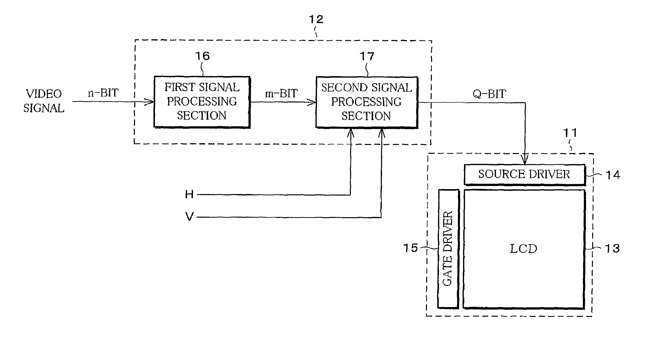
[0032]The LCD apparatus in the present embodiment is, as shown in FIG. 1, provided with a display section 11 as display means for displaying an image in accordance with a video signal, and an image processing apparatus 12 for processing the video signal in accordance with the display properties of the display section 11.

[0033]The display section 11 includes an LCD 13, which has display properties of Q bit (Q: a natural number), that is, has tone gradation of 2° (the Qth power of 2), and a source driver 14 and a gate driver 15 as drive means for driving the LCD 13.

[0034]The source driver 14, upon receipt of a video signal that has been processed by the image processing apparatus 12, sends a voltage, which varies depending on the inputted video signal, to a source...


PUM


Abstract

An image processing apparatus of the present invention comprising (a) a first signal processing circuit for applying gamma correction to an n-bit (n: a natural number) digital signal inputted as a video signal and for converting the n-bit digital signal into an m-bit (m>n, m: a natural number) digital signal, and (b) a second signal processing circuit for adding a noise signal, which is used for pseudo contour reduction, into the m-bit digital signal from the first signal processing circuit and for outputting a Q-bit (Q: a natural number) digital signal, which is obtained from rounding off a less significant (m−Q) bit (Q≦n) from the m-bit digital signal, to a display section.

Description

FIELD OF THE INVENTION[0001]The present invention relates to an image processing apparatus, in which a digital signal is inputted as a video signal, for use in a digital image display apparatus for displaying a digital image, and an image display apparatus provided with the image processing apparatus.BACKGROUND OF THE INVENTION[0002]Conventionally, gamma correction is usually applied to a digital video signal inputted into a digital image display apparatus in order to improve display properties to the level of that of Cathode Ray Tube (CRT) apparatus.[0003]However, pseudo contour is caused on the display image when inputting the gamma-corrected video signal into the digital image display apparatus without any treatment, thus resulting in lower display quality.[0004]Therefore, for example, disclosed in Japanese Unexamined Patent Publication Tokukaihei No. 9-185707 (published on Jul. 15, 1997) is technology for reducing the pseudo contour due to the gamma correction. The technology em...

Claims


Application Information

Patent Timeline
Patent Type & Authority Patents(United States)
IPC IPC(8): G09G5/02G06T5/00G06T11/00G09G3/20G09G3/36G09G5/00H04N5/202H04N5/21H04N5/66
CPCG09G3/20G09G3/2048G09G3/2092H04N5/202H04N5/66G09G3/2059G09G3/3614G09G3/3648G09G2320/02G09G2320/0242G09G2320/0276G09G2320/0285G09G2320/0606G09G2320/0626G09G2320/0673G09G3/2011H04N5/21
Inventor YOSHIDA, YASUHIROFURUKAWA, HIROYUKI
Owner III HLDG 12 LLC
Why Eureka
Try Eureka