Image heating apparatus including rotary member with metal layer

a heating apparatus and metal layer technology, applied in the field of image heating apparatus, can solve the problems of excessive heat in the convex portion of the recording medium s, the sticking of the fixing film to the fixing film, and the long time required by the roller system for elevating the roller surface, etc., to achieve the effect of suppressing the uneven heating of the toner imag

Active Publication Date: 2006-02-21
CANON KK
View PDF8 Cites 43 Cited by
  • Summary
  • Abstract
  • Description
  • Claims
  • Application Information

AI Technical Summary

Benefits of technology

[0013]The present invention has been made in consideration of the foregoing, and an object of the present invention is to provide an image heating apparatus capable of suppressing an uneven heating of a toner image even in case a recording medium after passing a nip portion generates an undulation.
[0010]In order to avoid such trouble, it is necessary, in the heat fixing apparatus of the film heating type, to facilitate the separation of the fixing film 114 and the recording medium at a downstream side of the pressed nip in the conveying direction of the recording medium. For this purpose, as shown in FIG. 5, a separating projection 112a may be provided on the heater holder 112 at a downstream end of the heater 113. In the heat fixing apparatus of the film heating type, the curvature at the separating portion is made larger in order to prevent the sticking jam. In such configuration, the fixing film 114 and the recording medium remain in close contact over a long range without pressure even after passing the nip where the pressure roller 115 is in contact, as shown in FIG. 5. However, there results a following drawback. In a portion immediately after a recording medium S is discharged from the nip of the fixing film 114 and the pressure roller 115, as shown in FIGS. 6 and 7, the recording medium S shows a thermal expansion simultaneous with the release of the recording medium S from the constriction in the nip, and an undulation Sa in the longitudinal direction appears in the recording medium S because of a difference in the expansion rate between a portion constricted in the nip and a released portion after the nip. In such undulated state, a convex portion of the recording medium S contact longer, than a concave portion, with the fixing film 114. As a result, a convex portion of the recording medium S tends to receive an excessive heat in comparison with a concave portion, as shown in FIG. 7. Such undulation Sa is more noticeable in a recording medium S of a resinous film such as an OHP sheet or a glossy film, but also appears in plain paper or glossy paper.

Problems solved by technology

However, the fixing apparatus of such heat roller system has required a very long time for elevating the roller surface to a fixing temperature because of a large heat capacity of the roller.
If the fixing film 114 remains in contact with the recording medium, a curvature at a separating portion decreases, thereby tending to cause a sticking jam to the fixing film 114.
However, there results a following drawback.
However, in case of employing a fixing sleeve constituted of an elastic layer, a releasing layer and a metal film, having a certain heat capacity (for example a heat capacity per unit area of 0.1 J / cm2·K), a convex portion in an undulation Sa generated in the recording medium S receives excessive heat in comparison with a concave portion.

Method used


Image

  • Image heating apparatus including rotary member with metal layer
  • Image heating apparatus including rotary member with metal layer
  • Image heating apparatus including rotary member with metal layer

Examples


Embodiment Construction

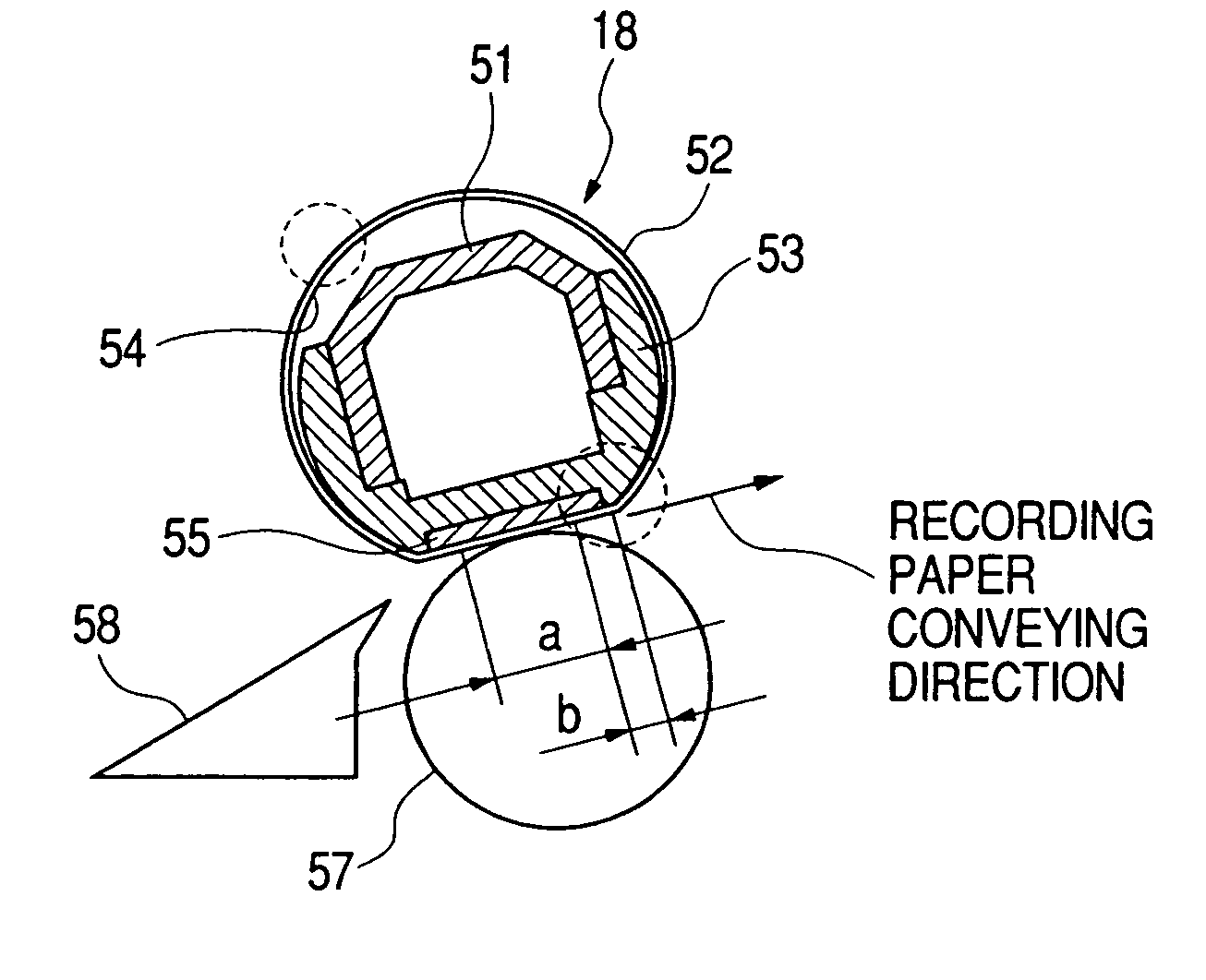
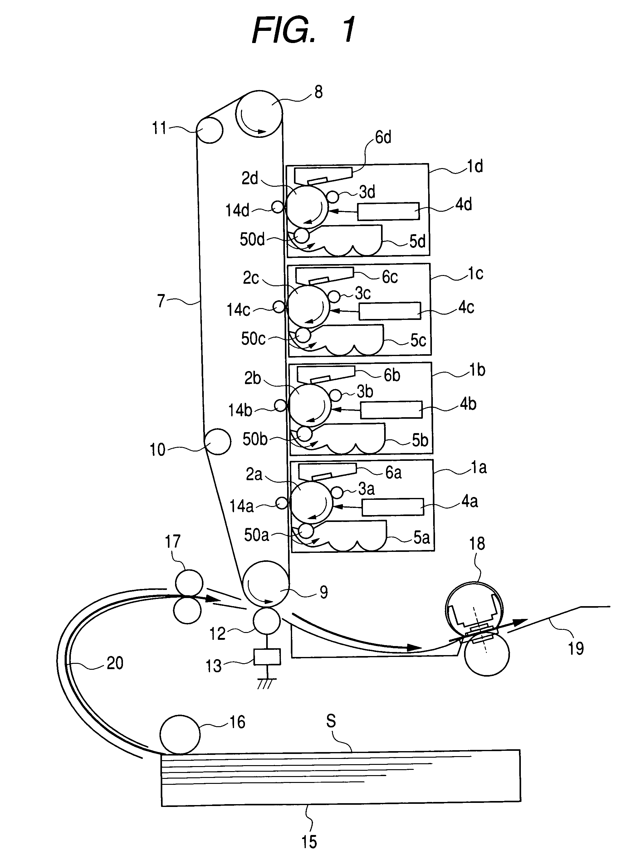
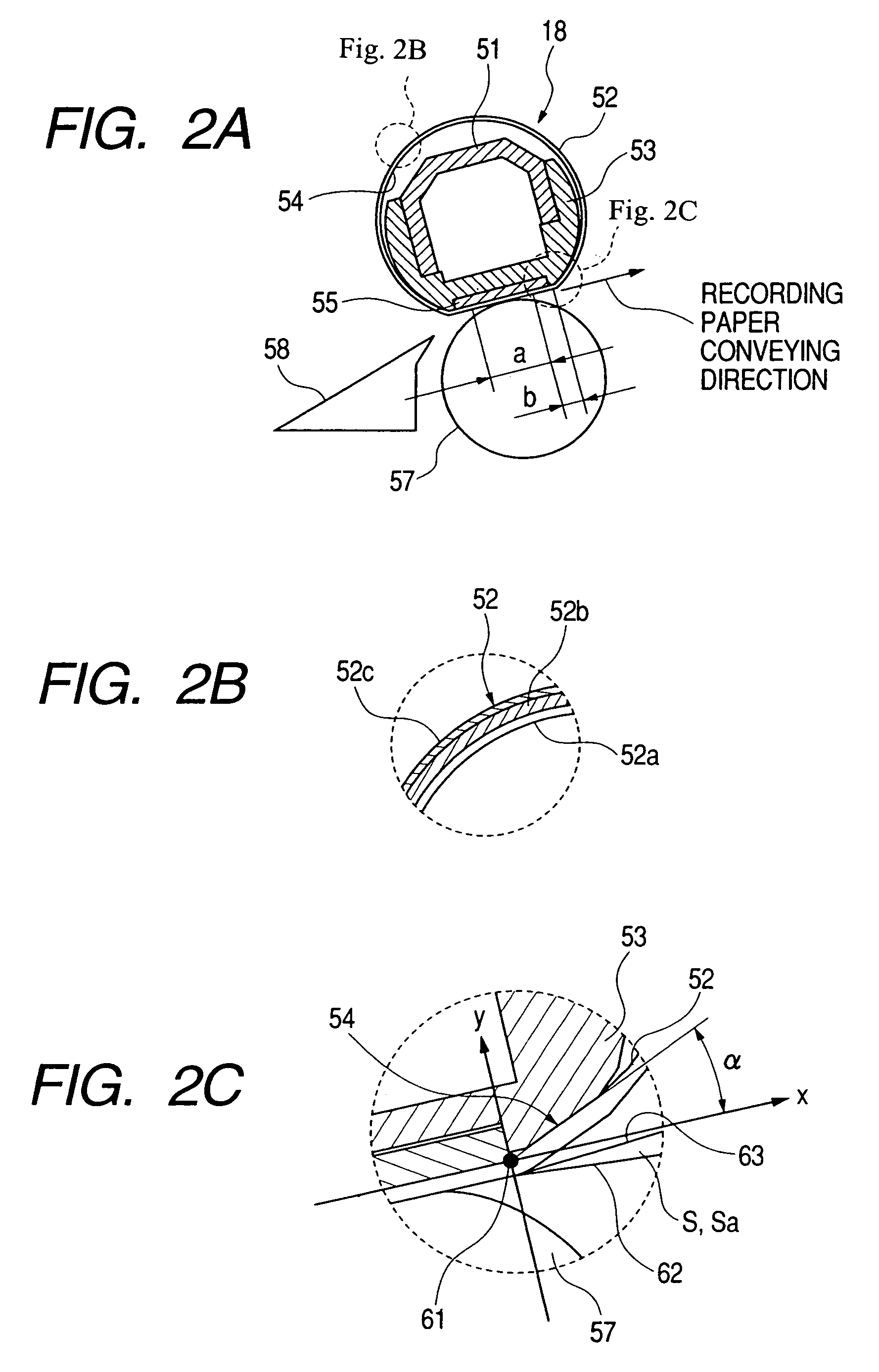
[0031]In the following, there will be explained, with reference to accompanying drawings, an embodiment of an image forming apparatus utilizing a fixing apparatus of the present invention. FIG. 1 is a view showing an example of the image forming apparatus, while FIGS. 2A, 2B and 2C are schematic views of a fixing apparatus, and FIG. 3 is a table showing experimental results of an optical transparency, a separability for the recording medium and an endurance of the fixing film as a function of a separation angle α. In the following, there will be explained at first an entire configuration of an image forming apparatus and then a configuration of a fixing apparatus.

(Image Forming Apparatus)

[0032]The image forming apparatus of the present embodiment is a full-color image forming apparatus employing an electrophotographic process, and is provided with four process stations 1a to 1d which are arranged substantially linearly in a substantially vertical direction for forming images of resp...


PUM


Abstract

An image heating apparatus for heating an image formed on a recording material, including a heater, a holder for holding the heater, a rotating member rotating around the holder and being flexible and having a metal layer, and a pressure roller forming a nip with the heater across the rotating member, wherein the rotating member moves detaching from the pressure roller just after passing through a downstream end portion of a surface of the heater opposed to the pressure roller. Thus, an uneven heating of a toner image can be prevented even in a case where the recording material becomes undulated after passing the nip portion.

Description

BACKGROUND OF THE INVENTION[0001]1. Field of the Invention[0002]The present invention relates to an image heating apparatus for heating an image on a recording material, and more particularly to an image heating apparatus adapted for use as a heat fixation device to be employed in a copying machine or a printer.[0003]2. Related Background Art[0004]As a fixing apparatus to be mounted in an image forming apparatus such as a copying apparatus, there has been employed a heat roller system as shown in FIG. 4. Such system has a basic configuration including a heating roller 102 for example of a metal, provided therein with a heater 101, and an elastic pressure roller 103 maintained in pressed contact therewith, and introducing and passing a recording medium, constituting a member to be heated, in a nip portion of such paired rollers for conveying therethrough, thereby fixing a toner image under heating and a pressure.[0005]However, the fixing apparatus of such heat roller system has requi...

Claims


Application Information

Patent Timeline
Patent Type & Authority Patents(United States)
IPC IPC(8): G03G15/20
CPCG03G15/2039G03G2215/2035G03G15/2032
Inventor UCHIDA, MICHIOUMEZAWA, MASAOANDO, ATSUTOSHITSUCHIYA, TOSHIKAZU
Owner CANON KK
Why Eureka
Try Eureka