Memory controller with power management logic

a memory controller and logic technology, applied in the direction of memory adressing/allocation/relocation, instruments, liquid/fluent solid measurement, etc., can solve the problems of high latencies and the inability of the dependent bank to operate independently of its neighbors

Inactive Publication Date: 2006-02-21
RAMBUS INC
View PDF7 Cites 127 Cited by
  • Summary
  • Abstract
  • Description
  • Claims
  • Application Information

AI Technical Summary

Benefits of technology

[0018]Additional logic converts the first information, fullness information and miss signal into at least one command selection signal and at least one update control signal. Cache update logic updates information stored in the cache in accordance with the at least one update control signal. Command issue circuitry issues power state commands and access commands to the dynamic memory devices in accordance with the at least one command selection signal and the address in the memory access request.

Problems solved by technology

Lower power states are typically characterized by higher latencies, because of the time required for the memory device to return from the low power state to a normal mode of operation.
But because it shares sense amp arrays with adjacent banks (called neighbor banks or just neighbors), a dependent bank cannot operate independently of its neighbors.

Method used


Image

  • Memory controller with power management logic
  • Memory controller with power management logic
  • Memory controller with power management logic

Examples


Embodiment Construction

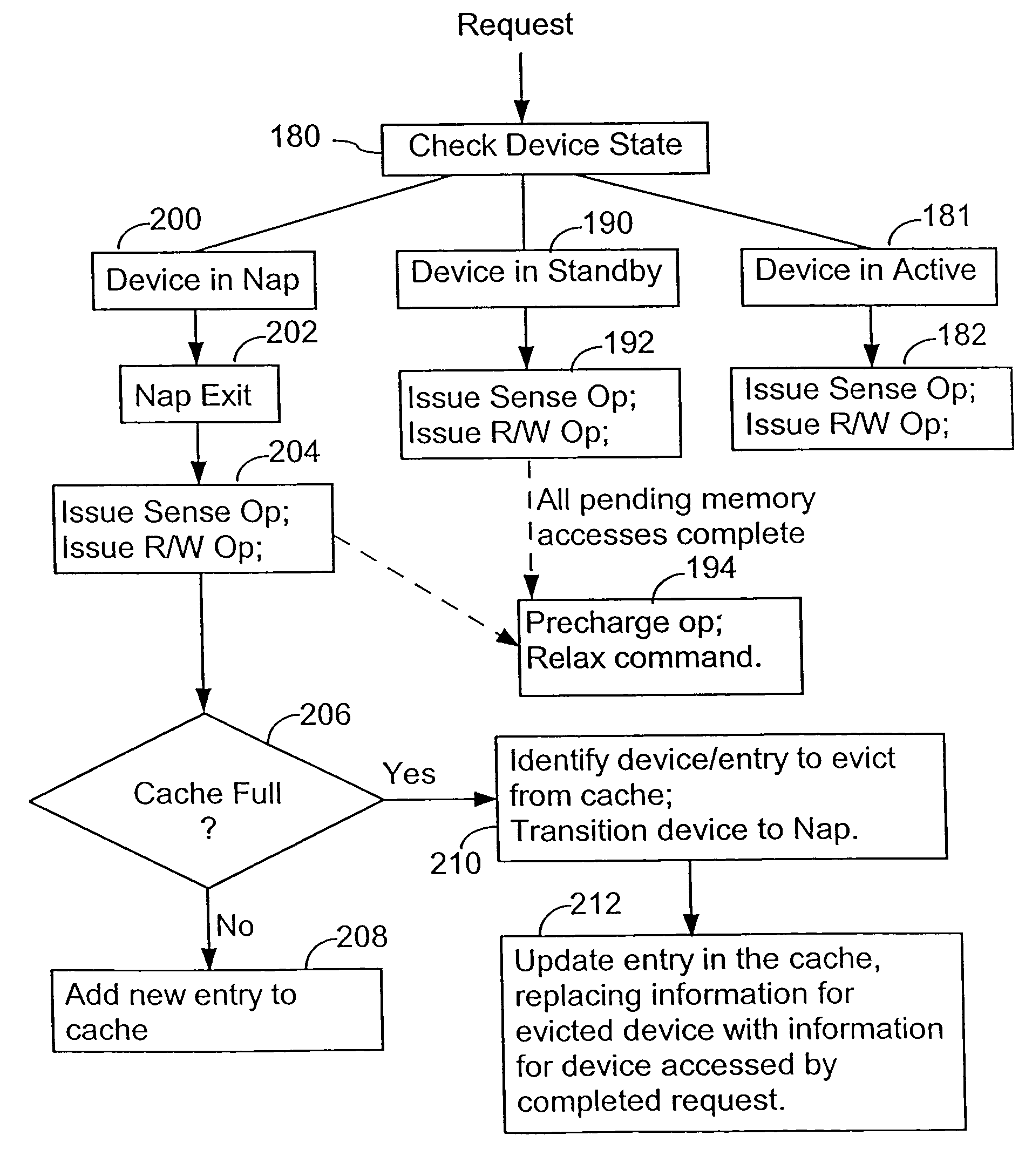
[0029]As indicated in the summary, depending on the particular memory devices being controlled, the number of possible power states and the exact definition of those power states will vary, but will generally includes at least a first (active) state, a second (mid-power) state, and a third (low power) state, where the second power state uses less power than the first power state, and the third power state uses less power than the second. While the invention will be described with respect to Active, Standby and Nap states, in other implementations these power states may be replaced by first, second and third power states, as well as other additional power states, whose definitions are different from those of Active, Standby and Nap.

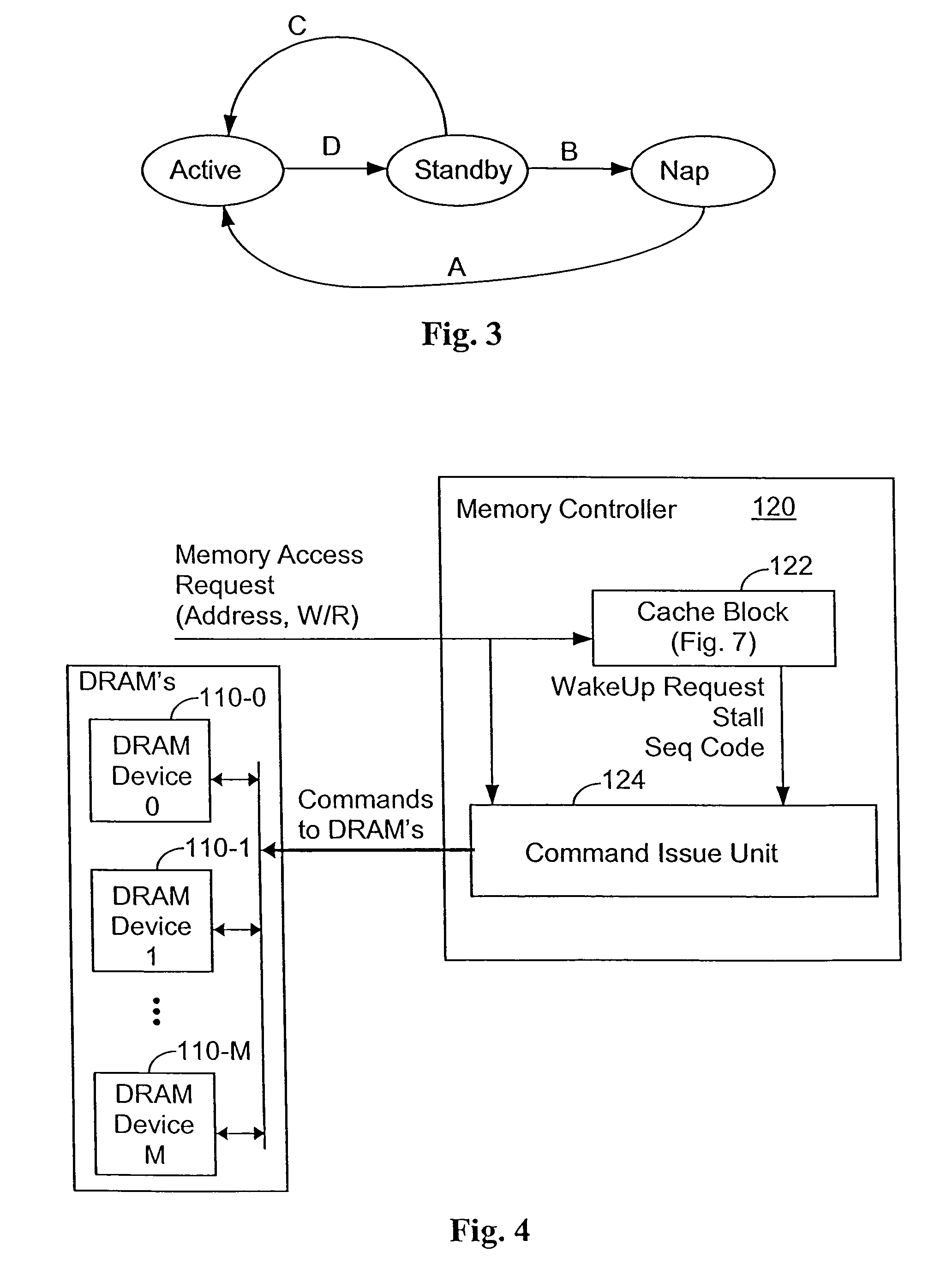
[0030]Referring to FIG. 3, a memory device in the Active state may be “relaxed” to the Standby state to reduce power consumption, and then put in a Nap state to further reduce power consumption. Any memory device in the Standby state may transition directl...


PUM


Abstract

A memory controller controls access to, and the power state of a plurality of dynamic memory devices. A cache in the memory controller stores entries that indicate a current power state for a subset of the dynamic memory devices. Device state lookup logic responds to a memory access request by retrieving first information from an entry, if any, in the cache corresponding to a device address in the memory access request. The device state lookup logic generates a miss signal when the cache has no entry corresponding to the device address. It also retrieves second information indicating whether the cache is currently storing a maximum allowed number of entries for devices in a predefined mid-power state. Additional logic converts the first and second information and miss signal into at least one command selection signal and at least one update control signal. Cache update logic updates information stored in the cache in accordance with the at least one update control signal. Command issue circuitry issues power state commands and access commands to the dynamic memory devices in accordance with the at least one command selection signal and the address in the memory access request.

Description

[0001]This application is a continuation of U.S. utility patent application no. 10 / 369,301, filed Feb. 18, 2003, now U.S. Pat. No. 6,754,783 which is a continuation of U.S. utility patent application Ser. No. 09 / 907,338, Jul. 16, 2001, now U.S. Pat. No. 6,523,089 B2, which claimed priority to U.S. provisional patent application 60 / 219,358, filed Jul. 19, 2000.[0002]The present invention relates generally to memory controllers for controlling and managing access to dynamic memory devices, and particularly to power management logic for enabling the memory controller to maximize memory performance while keeping total energy usage within a predefined budget or minimized (e.g., for battery-operated systems).BACKGROUND OF THE INVENTION[0003]The main memory of a computer, mobile device, or other computer controlled system may be populated by a number of DRAM (dynamic random access memory) devices, such as Rambus “Direct RDRAM” devices. In some applications there is a need to limit the amou...

Claims


Application Information

Patent Timeline
Patent Type & Authority Patents(United States)
IPC IPC(8): G06F12/00G06F1/32G06F12/02G11C11/4074
CPCG06F1/3203G06F1/3275G06F12/0215G11C11/4074Y02B60/1228Y02B60/1225G06F2212/1028Y02D10/00
Inventor TSERN, ELY K.SATAGOPAN, RAMPRASADBARTH, RICHARD M.WOO, STEVEN C.
Owner RAMBUS INC
Why Eureka
Try Eureka