Crimp tool for strain relief connector and method of forming a strain relief connector

a technology of crimping tool and connector, which is applied in the direction of manufacturing tools, instruments, optical elements, etc., can solve the problems of changing the optical characteristics of the optical fiber, affecting the lateral flow the length of the crimp is short relative to the diameter of the jacket material, so as to achieve a large frictional area

Inactive Publication Date: 2006-02-28
HUBBELL INC
View PDF18 Cites 16 Cited by
  • Summary
  • Abstract
  • Description
  • Claims
  • Application Information

AI Technical Summary

Benefits of technology

[0009]Accordingly an object of the present invention is to provide a strain relief connector for a fiber optic cable that has a relatively large frictional area between the inner surface of the crimp sleeve and the cover layer of the fiber optic cable for a strong reliable crimp connector.
[0010]Another object of the present invention is to provide a strain relief connector for a fiber optic cable that has a crimped configuration that allows for substantial lateral flow of the cover layer, putting substantially no longitudinal pressure or strain on the optical fiber.
[0011]Still another object of the present invention is to provide a strain relief connector for a fiber optic cable that has a crimp sleeve with a length that is long relative to the diameter of the cover layer, providing a large area of frictional engagement between the cover layer and crimp sleeve and the cover layer and optical fiber.
[0012]Yet another object of the present invention is to form a strain relief connector that has a cover, which can be optimally positioned within a sleeve.
[0013]Still yet another object of the present invention is to provide a crimping tool and strain relief connector that provide optimal crimping of the sleeve and cover in the connector.

Problems solved by technology

Conventional crimping methods do not allow adequate lateral flow of the jacket material, in other words, the jacket material does not substantially flow in a direction perpendicular to the longitudinal axis of the crimp sleeve.
Longitudinal flow places tension on the optical fiber, possibly causing damage to or failure of the optical fiber, or changing its optical characteristics.
In addition, conventional crimping methods have a crimp length that is short relative to the diameter of the jacket material.
This short length results in a small area of frictional contact between the inner surface of the crimp sleeve and the outer surface of the buffer material and may make failure of the connector more likely under tensile or thermal stress.
Furthermore, when assembling and crimping conventional connectors, it can be difficult to properly position the polymer cover within the metal tube or sleeve.
Also, since the polymer cover is generally disposed within the sleeve, it can be difficult to ascertain the exact location of the polymer cover relative to the sleeve.

Method used


Image

  • Crimp tool for strain relief connector and method of forming a strain relief connector
  • Crimp tool for strain relief connector and method of forming a strain relief connector
  • Crimp tool for strain relief connector and method of forming a strain relief connector

Examples


embodiment

of FIG. 14–17

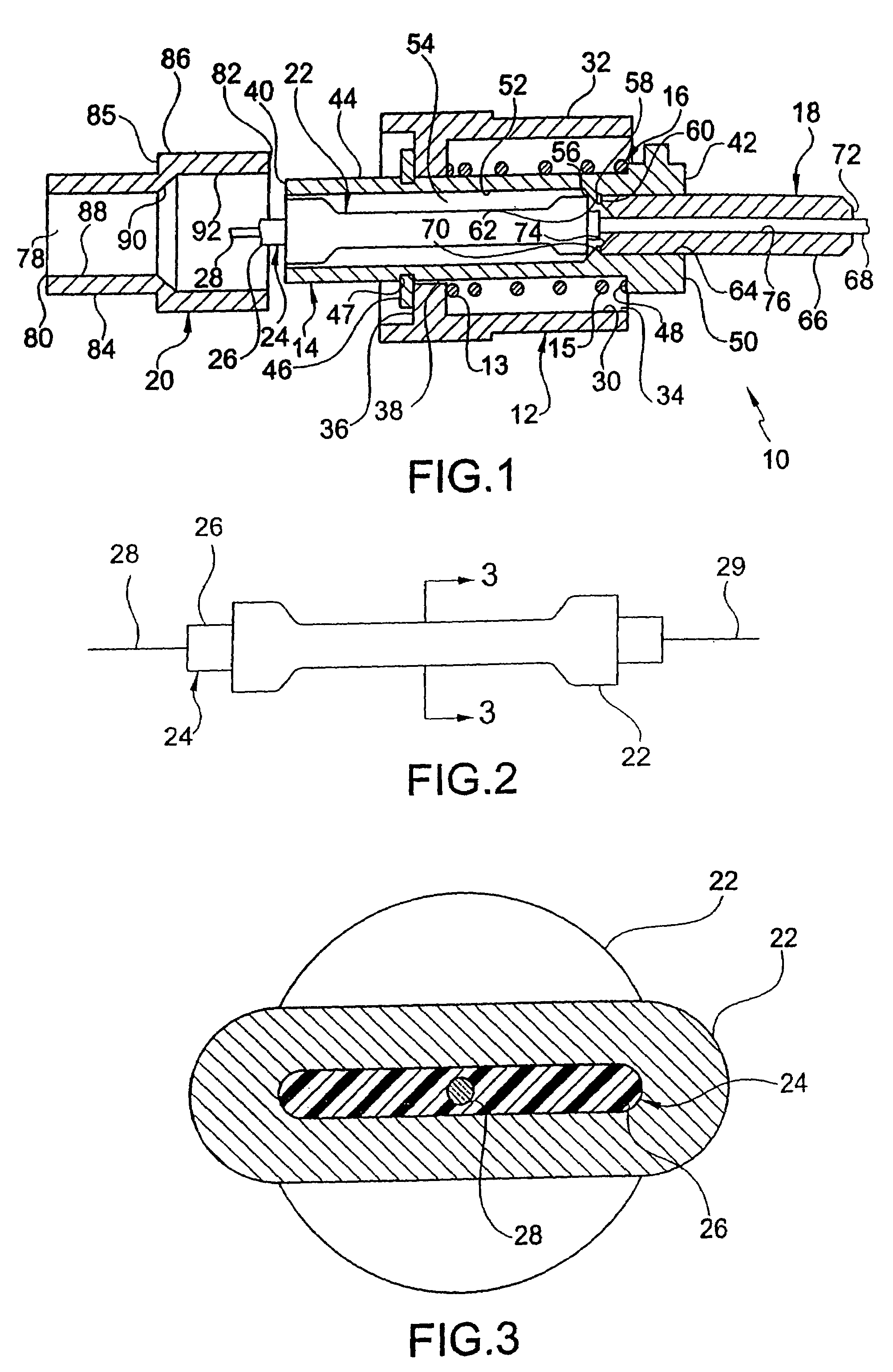
[0073]Crimp sleeve 522 is substantially similar to sleeve 22 described above. However, as shown in FIG. 14, the fiber optic cable 524 has an optical fiber 526 of a 125 micron (0.125 mm) diameter 528. Surrounding the optical fiber is preferably an acrylate polymer coating 530 that has of a 250 micron (0.250 mm) outside diameter 532. However, the coating may be any suitable polymer. Surrounding the polymer coating 530 is a buffer material or layer 534 of a 900 micron (900 mm) outer diameter 536. Preferably the buffer layer is polyvinyl chloride (PVC), but may be any other suitable material. Similar the cover 26 above, outer diameter 536 of buffer layer 534 is substantially smaller than inner diameter 538 of sleeve 522.

[0074]The crimping method is substantially similar to the above described crimping method and results in the deformed width substantially greater than the deformed height. As seen in FIG. 15, the internal portion of the present embodiment produces substantia...


PUM

PropertyMeasurementUnit
outer diameteraaaaaaaaaa
inner diameteraaaaaaaaaa
diameteraaaaaaaaaa

Abstract

Crimp tool is for and a method forms a strain relief connector including an optical fiber, a cover enclosing the optical fiber. The cover has an inner surface, an outer surface, a first end and a second end, the first end having a tapered portion that extends radially outwardly. A sleeve surrounds the cover and has a first inner volume and a first interior shoulder, a portion of the outer surface of the tapered portion abuts the first interior shoulder. The sleeve and the cover are simultaneously compressed forming a compressed portion. The cover and the sleeve are deformed such that the cover substantially fills the first inner volume of the sleeve.

Description

REFERENCE TO RELATED APPLICATION[0001]This application is a division of U.S. patent application Ser. No. 10 / 115,429 entitled Strain Relief Connector for Fiber Optic Cable and Method of Making Same and filed Apr. 4, 2002 now U.S. Pat. No. 6,726,373, and is a continuation-in-part of U.S. patent application Ser. No. 09 / 565,489, entitled Strain Relief Connector for Fiber Optic Cable and Method of Making Same and field May 5, 2000, now U.S. Pat. No. 6,390,688, the subject matter of each of which is hereby incorporated by reference.FIELD OF THE INVENTION[0002]The present invention relates to a crimping tool for and a method for forming a non-adhesive strain relief connector for a fiber optic cable. More particularly, the present invention relates to an optical fiber and cover that are disposed with in a metal sleeve, the cover having a tapered portion that positions the cover within the sleeve. The cover and sleeve are simultaneously compressed such that the cover substantially fills the ...

Claims


Application Information

Patent Timeline
Patent Type & Authority Patents(United States)
IPC IPC(8): B23P19/00G02B6/36G02B6/38
CPCG02B6/2558G02B6/3838G02B6/3846G02B6/3887G02B6/3898G02B6/3807Y10T29/53226G02B6/3821G02B6/3857G02B6/3869G02B6/3894Y10T29/53222Y10T29/49181Y10T29/53213Y10T29/49183G02B6/3809G02B6/382G02B6/3888
Inventor LUTZEN, JON A.MONTGELAS, RUDOLPH A.MILLER, ALAN C.
Owner HUBBELL INC
Why Eureka
Try Eureka