
Wire payout

a wire and wire technology, applied in the field of wire payout, can solve the problems of significant down time, adversely affecting the welding process, and a large amount of wire distortion and tangling, and achieve the effect of convenient use in the field and economic manufactur

Inactive Publication Date: 2006-02-28
LINCOLN GLOBAL INC
View PDF12 Cites 48 Cited by
  • Summary
  • Abstract
  • Description
  • Claims
  • Application Information

AI Technical Summary

Benefits of technology

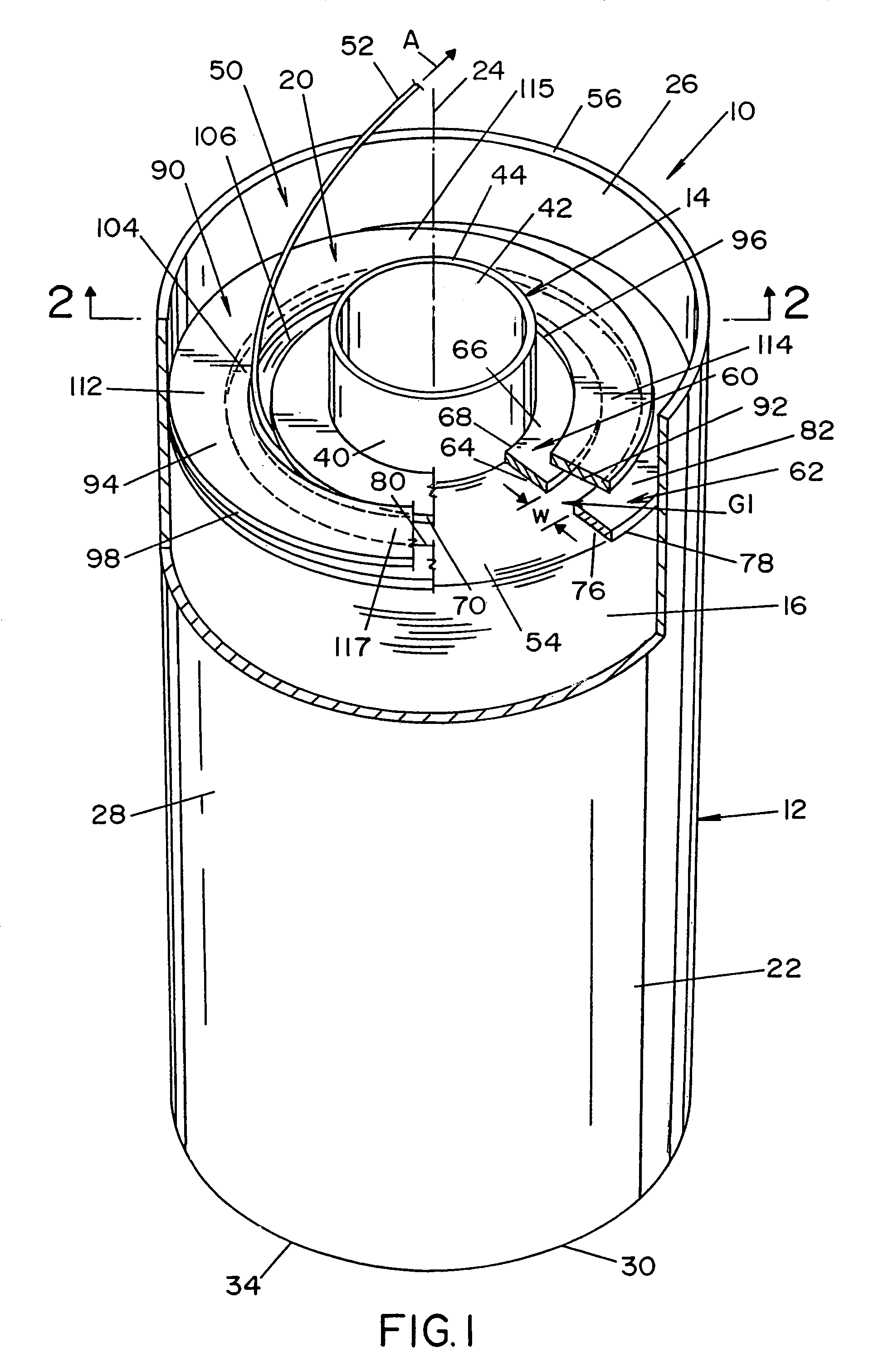
[0012]In accordance with the present invention, provided is a payout for use in connection with a welding wire package which includes at least two separate and independent retaining rings of a light weight disposable material which cooperably control the payout of the welding wire. In this respect, a payout in accordance with the present invention includes at least one ring which rests on top of the coil of wire and which prevents the coil of wire from springing upwardly, and a second ring which at least partially rests on the one ring and which is spaced above the top of the coil of wire. The two rings, one of which may be a floating ring, cooperatively control the payout of the wire from the wire coil. By utilizing at least two rings, one of which may move independently of the other, simple ring structures can be used to optimize restraint of the wire from springing upwardly and to improve control of the payout of the wire from the wire coil.
[0013]A payout according to one aspect of the present invention can utilize both a radially inner and a radially outer stationary ring, which rings engage the top of the coil of wire and are radially spaced from one another to produce a circumferentially continuous wire payout gap therebetween which preferably is radially centrally of the inner and outer sides of the coil wire. In another embodiment, a floating ring is of the size and shape to partially cover the gap between the inner and outer rings. The wire, as it is payed out of the wire coil package, passes between one of the edges of the inner or outer rings and one of the edges of the floating ring which rotates about the coil axis and eccentrically relative thereto during payout. As a result, as stated above, simple payout or ring designs which are easy to manufacture can be used, and the individual rings can be designed for its specific purpose. This can include different material choices and different textures used along the guiding edges or other surfaces without requiring complex components or materials.
[0015]The primary object of the present invention is the provision of a payout for a wire coil package which allows the continuous and uninterrupted withdrawal of a welding wire from the package smoothly and without tangling.
[0020]Another object is the provision of a welding wire package of the foregoing character which utilizes components that are economical to manufacture, easy to use in the field and which are economically disposable.

Problems solved by technology

Furthermore, welding applications wherein large quantities of welding wire are consumed necessitate welding wire packages which contain large quantities of a continuous welding wire.
It is well known that wire has a tendency to seek a predetermined natural condition which can adversely affect the welding process.
To help in this respect, the manufacturers of welding wire produce a wire having natural cast wherein if a segment of the wire was laid on the floor, the natural shape of the wire would be essentially a straight line; however, in order to package large quantities of the wire, the wire is coiled into the package which can produce a significant amount of wire distortion and tangling as the wire is dispensed from the package.
Both tangling or breaking of the welding wire can cause significant down time while the damaged wire is removed and the wire is re-fed into the wire feeder.
However, when the welding wire pays out of the package, the walls of the package loose their influence on the wire and the wire is forced toward its natural cast.
This causes the portion of the wire which is being withdrawn from the package to loosen and tend to spring back into the package thereby interfering and possibly becoming tangled with other convolutions of wire.

Method used


Image

  • Wire payout
  • Wire payout
  • Wire payout

Examples


Embodiment Construction

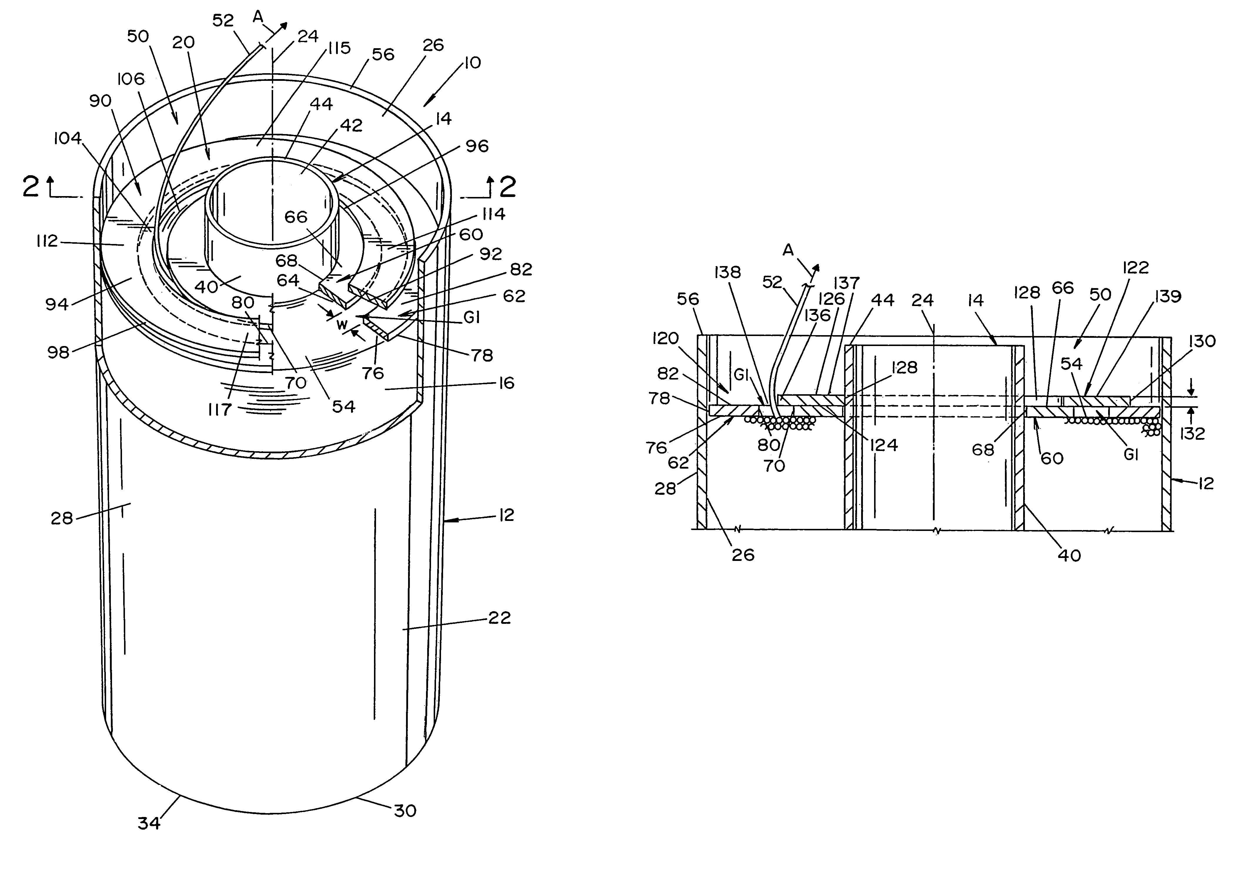
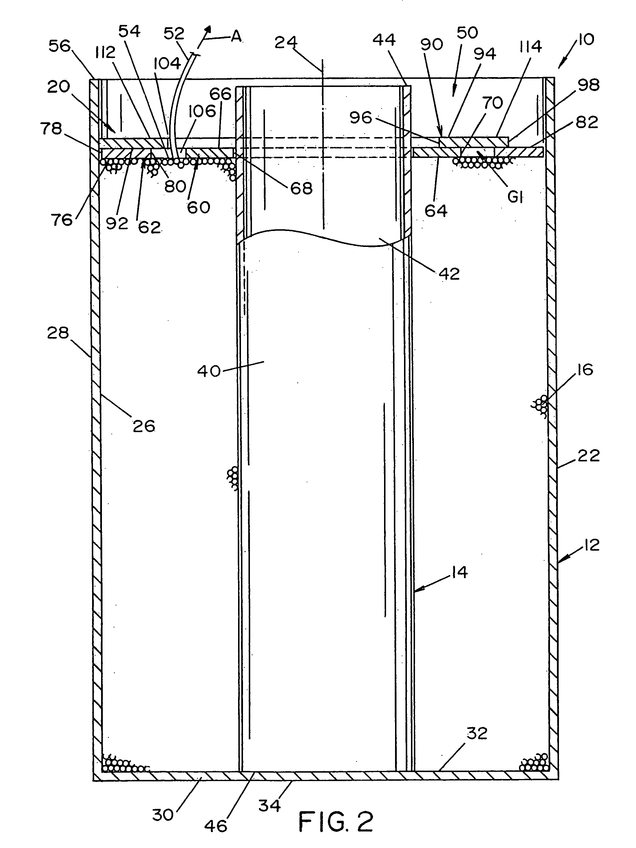
[0034]Referring now in greater detail to the drawings wherein the showings are for the purpose of illustrating preferred embodiments of the invention only, and not for the purpose of limiting the invention, FIG. 1–3 illustrate a welding wire package 10 which is shown as a welding wire drum and will be described hereinafter with relation to such a wire drum even though the invention of this application can be used in connection with other styles of welding wire packages. Welding wire package 10 includes a wire drum 12, an inner core 14, a coil of wire 16 and a payout 20. Wire drum 12 has a cylindrical outer drum body 22 which is coaxial with a drum axis 24 and which has an inwardly facing surface 26 and an outwardly facing surface 28. Wire drum 12 further includes a drum bottom 30 having an upwardly facing surface 32 and an outside surface 34. Wire drum 12 can be made from any well-known packaging material such as paper, plastic, wood or steel. However, it must be able to withstand t...


PUM


Abstract

A payout for controlling the unwinding of a coil of wire from a wire drum which has an outer drum body and an inner core substantially coaxial with the drum body includes a first planar ring juxtaposed the top of the wire coil and having a first inner edge closely adjacent to the core and a first outer edge spaced from the first inner edge and a second planar ring juxtaposed the top of the wire coil and having a second outer surface closely adjacent the drum body and a second inner surface spaced from the first outer surface of the first ring to define a continuous circular gap above the wire coil such that the wire passes upwardly through the gap as it is withdrawn from the wire coil. A third ring overlies the first and second rings and is laterally displacable relative thereto and eccentrically relative to the drum axis to further control payout of the wire. The second and third rings along can be used to control payout of the wire.

Description

[0001]This is a continuation of application Ser. No. 10 / 083,426, filed Feb. 25, 2002, now U.S. Pat. No. 6,745,899.[0002]This invention relates to the art of dispensing wire and, more particularly to a wire payout for controlling the dispensing of large quantities of a continuous wire without tangling.INCORPORATION BY REFERENCE[0003]The present invention relates to feeding large quantities of a continuous wire from a container to a welding operation wherein the wire must be fed without tangling or interruption. Such containers are known in the art and are generally shown and described in Cooper U.S. Pat. No. 5,277,314; Cooper U.S. Pat. No. 5,819,934; Chung U.S. Pat. No. 5,746,380; Kawasaki U.S. Pat. No. 4,869,367 and Gelmetti U.S. Pat. No. 5,494,160. These patents are incorporated by reference herein as background information illustrating packaging and dispensing large quantities of wire. Further, these patents illustrate the importance of controlling the wire as it is being dispense...

Claims


Application Information

Patent Timeline
IPC IPC(8): B65D85/67B65H18/28B65H49/00B65D85/676B65H49/08B65H59/06
CPCB65D85/676B65H59/06B65H49/08
Inventor BARTON, DAVID J.
Owner LINCOLN GLOBAL INC
Learn More