

Wire bond fault detection method and apparatus
- Summary
- Abstract
- Description
- Claims
- Application Information
AI Technical Summary
Benefits of technology
Problems solved by technology
Method used
Image

Examples
Embodiment Construction
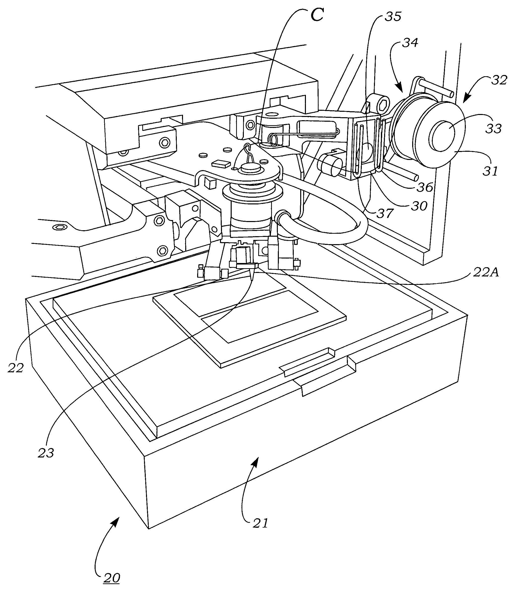
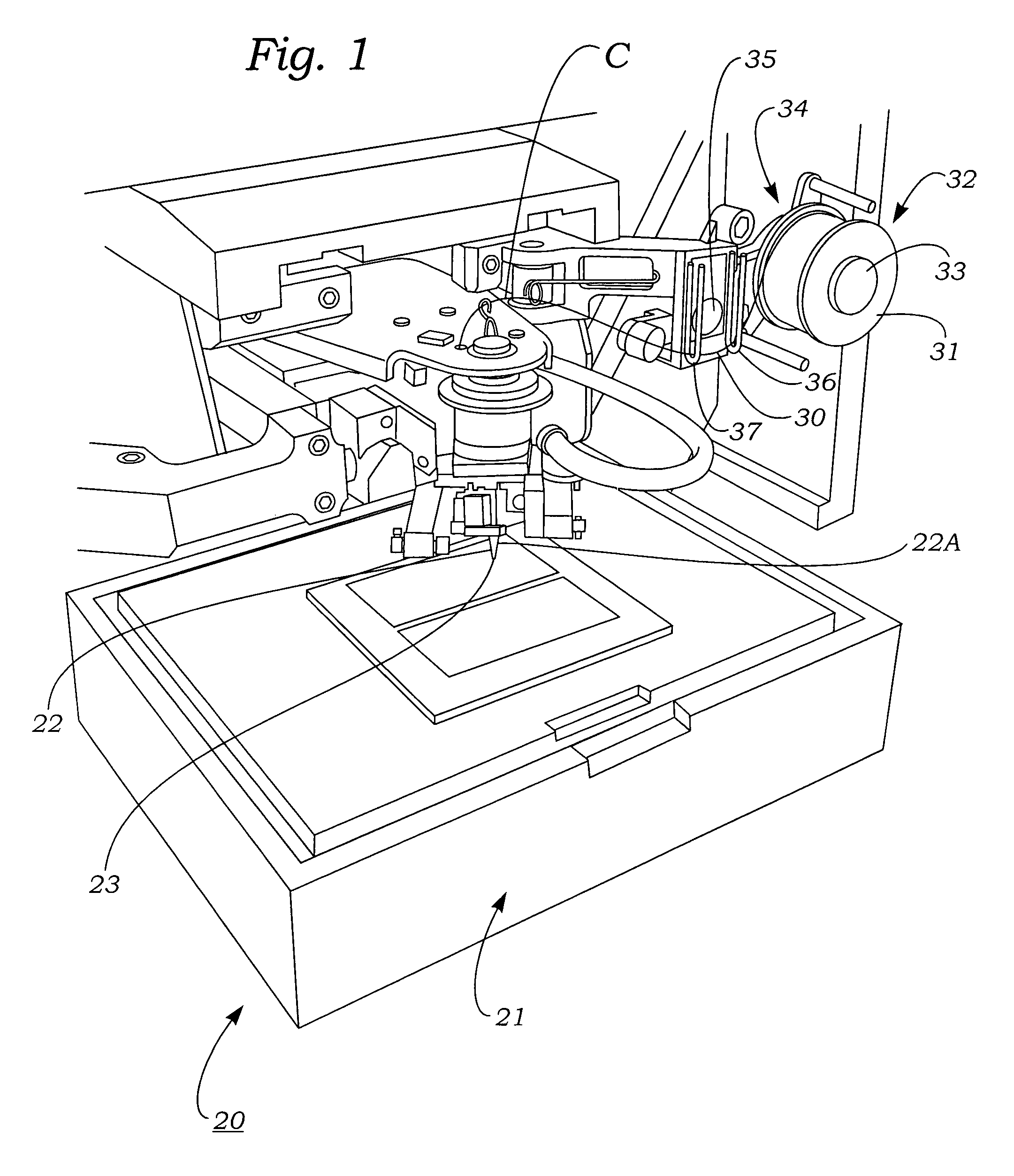
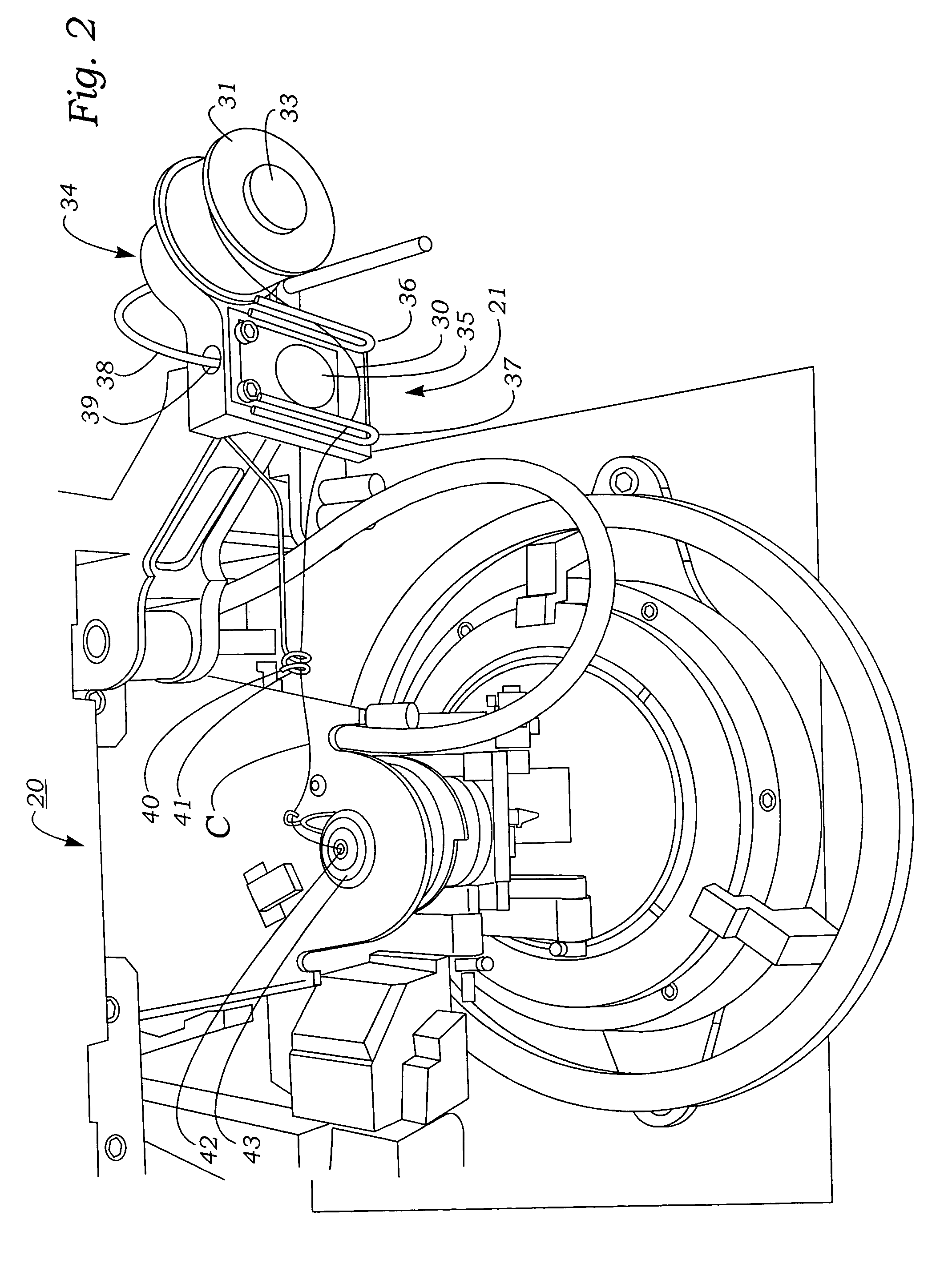
[0054]FIGS. 1–10C illustrate various aspects of a wire bond fault detection method and apparatus according to the present invention.
[0055]Referring first to FIGS. 1–4, a wire bond fault detection apparatus 20 according to the present invention is shown mechanically attached to an ultrasonic bonding machine 21, which it operates integrally with. As shown in FIG. 8, bonding machine 21 includes a bonding tool 22 which has an upper, generally cylindrically-shaped shank 22A and a lower, pointed end 23 which has disposed therethrough a wire feed bore 24 that has an upper entrance opening 25 and lower exit opening 26. Bonding wire C is drawn out of exit bore opening 26 and positioned below a foot 27 of tool tip 23, whereupon the tool is translated downwardly towards a workpiece A to press a length of wire C below the foot against a first bond site B1 on the workpiece. Ultrasonic energy is then applied to the upper, shank end 22A of tool 22, thus causing foot 27 and wire C to execute a hori...
PUM
| Property | Measurement | Unit |
|---|---|---|
| Length | aaaaa | aaaaa |
| Tension | aaaaa | aaaaa |
Abstract
Description
Claims
Application Information