Eureka AIR delivers breakthrough ideas for toughest innovation challenges, trusted by R&D personnel around the world.

Bodily sensed vibration generator system

a generator system and vibration technology, applied in the direction of mechanical vibration separation, motor/generator/converter stopper, dynamo-electric converter control, etc., can solve the problems of affecting the miniaturization of the system, the system cannot be mounted on portable telephones or portable game equipment to generate a variety of effective vibrations, and the system is difficult to set a vibration configuration freely. , to achieve the effect of easy vibration configuration setting

Active Publication Date: 2006-02-28
ALPS ALPINE CO LTD
View PDF5 Cites 41 Cited by
  • Summary
  • Abstract
  • Description
  • Claims
  • Application Information

AI Technical Summary

Benefits of technology

[0014]Embodiments of the invention provide a vibration generator system, which can generate vibrations at a frequency that can be bodily sensed by humans, while being small in size, and which makes setting of a configuration of vibrations easy.

Problems solved by technology

Also, while an increase in frequency of natural vibrations is conceivable for the sake of miniaturization, it is also difficult since the number of vibrations that can be bodily sensed by humans is in a relatively low frequency band.
Also, while the vibration generator system can generate simple vibrations based on the frequency of natural vibrations continuously or intermittently, it is not possible to freely set a configuration of vibrations.
Accordingly, it is not possible to mount the system on portable telephones or portable game equipments to generate a variety of effective vibrations.
Meanwhile, the conventional biased weight type vibration generator system is constructed to have a motor and a biased weight and so becomes large-sized, and it becomes necessary to firmly fix the motor in a manner to withstand vibrations caused by rotation of the biased weight, so that miniaturization of the system is impeded.
Also, since a large inertial force acts on the biased weight in rotation, it is hard to finely vary intensity (mode of vibration) of vibrations by giving various drive signals and modifying the rotating speed.
That is, the biased weight type vibration generator system involves a problem of a poor follow-up property of the vibration system for drive signals.

Method used


Image

  • Bodily sensed vibration generator system
  • Bodily sensed vibration generator system
  • Bodily sensed vibration generator system

Examples


Embodiment Construction

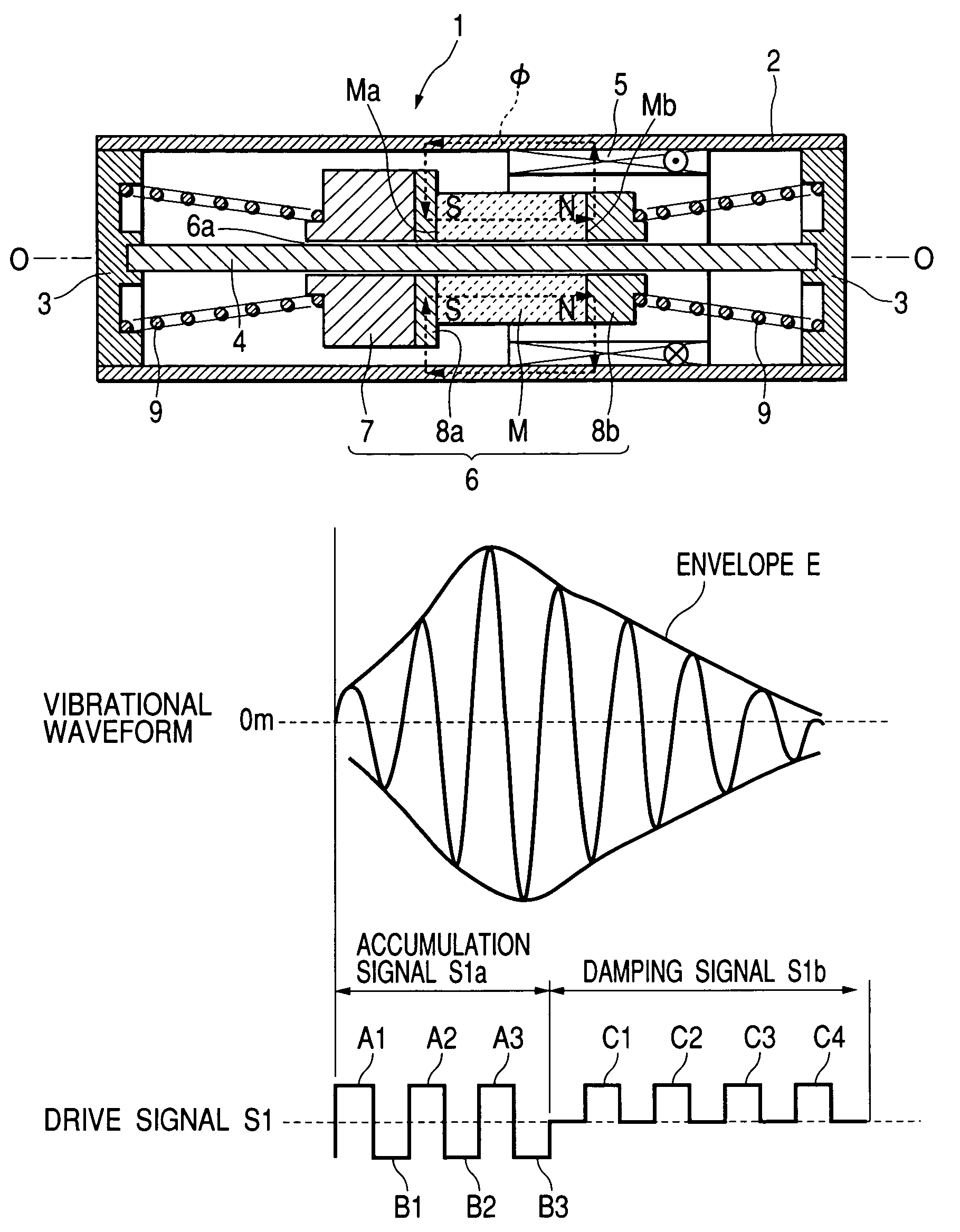
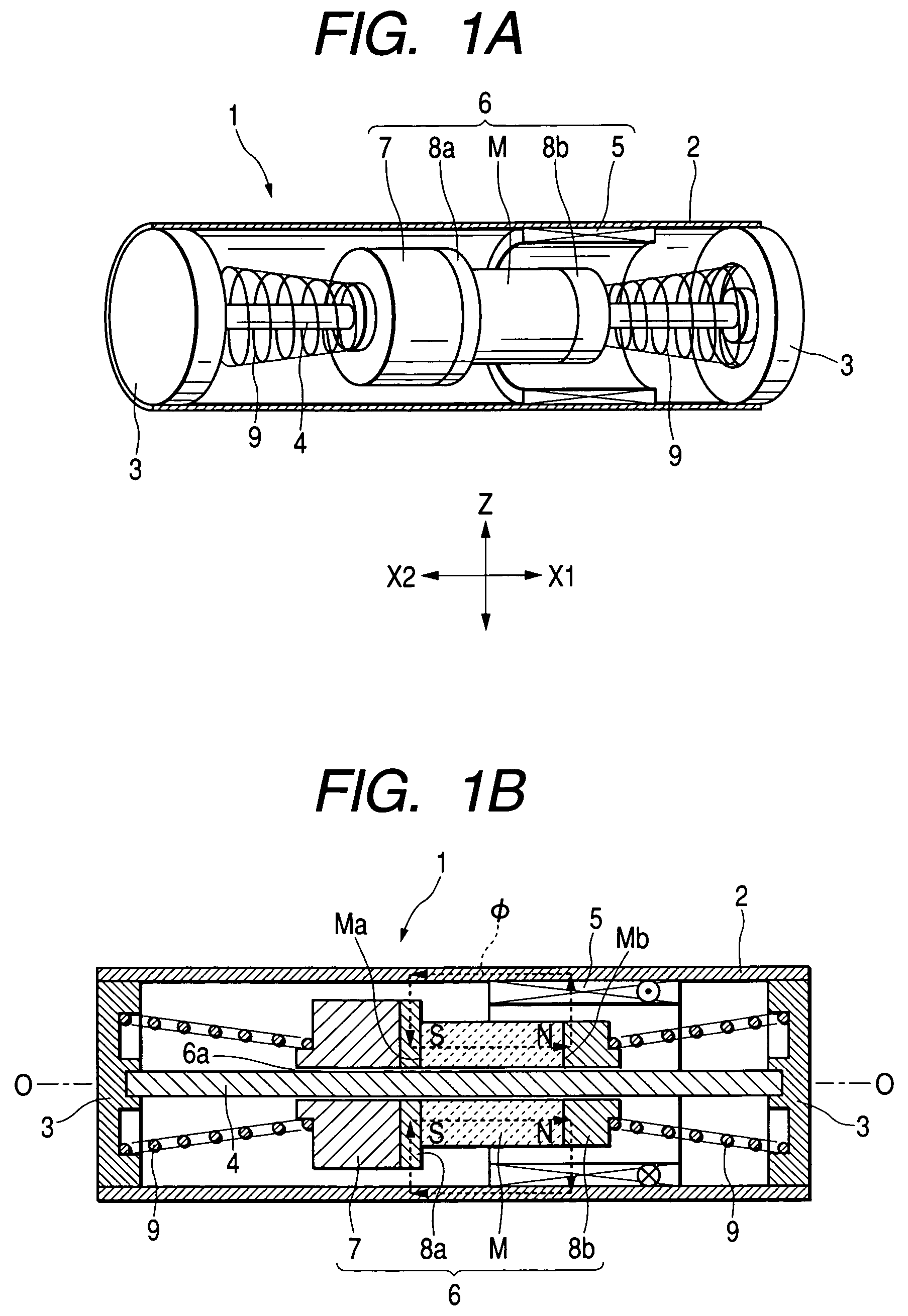
[0041]FIG. 1 shows an embodiment of vibration generating means, 1A being a perspective, cross sectional view, and 1B being a cross sectional view.

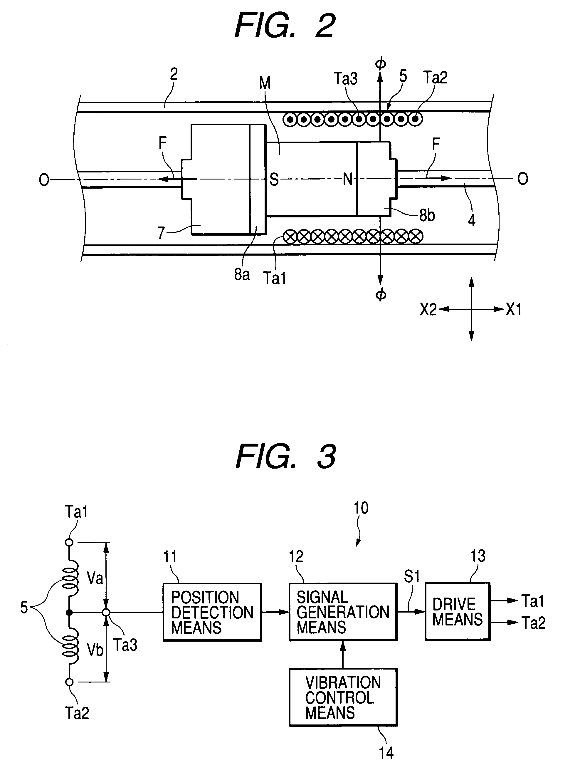
[0042]A vibration generator system according to the invention comprises vibration generating means 1 shown in FIG. 1 and control means shown in FIG. 3.

[0043]The vibration generating means 1 shown in FIG. 1 comprises a cylindrical-shaped casing 2 made of a magnetic substance as a support, and covers 3, 3 made of a non-magnetic substance and being mountable on both ends of the casing. A shaft 4 made of a non-magnetic substance is supported on inner surfaces of the covers 3, 3, the shaft 4 being in agreement with an imaginary center line O—O, which extends centrally of the casing 2 and the covers 3, 3.

[0044]A coil 5 is fixed to an inner wall of the casing 2. The coil 5 is formed by winding a length of covered copper wire, such as enameled wire or the like, in a cylindrical shape, and is fixed in a position somewhat to one (a X1 side in FIG. 1...


PUM


Abstract

A vibration generator system is capable of generating vibrations of a frequency that can be bodily sensed by humans, notwithstanding a small size, and making setting of a configuration of vibrations easy. When a drive signal composed of a set of an accumulation signal and a damping signal is given as a natural frequency of a movable body, a vibrational waveform of the movable body makes an envelope. Since a frequency of the envelope is in a lower frequency band than the natural frequency of the movable body, humans can surely sense vibrations. When the number of and a current quantity of excitation signals and reverse excitation signals included in the accumulation signal are changed and the number of and a current quantity of inhibition signals and reverse inhibition signals included in the damping signal are changed, the envelope can be changed in frequency and amplitude, so that it becomes possible to generate a variety of vibrations.

Description

[0001]This application claims the benefit of priority to Japanese Patent Application No. 2002-348993, herein incorporated by reference.BACKGROUND OF THE INVENTION[0002]1. Field of the Invention[0003]The present invention relates to a bodily sensed vibration generator system mountable on small-sized information terminal devices, such as portable telephones, PDA, portable game equipments, and so on, and more particular, to a bodily sensed vibration generator system, which is small in size and capable of realizing a variety of vibrations.[0004]2. Description of Related Art[0005]For example, Patent document 1 discloses an invention of a conventional vibration generator system.[0006]The vibration generator system may be used as a drive device for speakers, and in which a cylindrical-shaped coil is fixed on a side of a bottom surface of a housing and a magnetic field generator composed of a magnet and a yoke is elastically supported in a position opposed to an outer surface of the coil by...

Claims


Application Information

Patent Timeline
Patent Type & Authority Patents(United States)
IPC IPC(8): H02K3/00B06B1/02B06B1/04B06B1/14H02K33/16
CPCB06B1/0215H02K33/16B06B1/045
Inventor WAKUDA, HIROSHIKAWAUCHI, TAKAHIRO
Owner ALPS ALPINE CO LTD
Why Eureka
Eureka Blog
Learn More