Method and system for using a backbone protocol to improve network performance

a backbone protocol and network performance technology, applied in the field of methods and systems for using a backbone protocol, can solve the problems of not being able to compensate for all characteristics, not being able to guarantee the other end of datagrams, and not being able to achieve the effect of bandwidth limitations

Active Publication Date: 2006-02-28
HUGHES NETWORK SYST
View PDF9 Cites 32 Cited by
  • Summary
  • Abstract
  • Description
  • Claims
  • Application Information

AI Technical Summary

Benefits of technology

[0032]The method and system of the present invention utilize a backbone protocol which detects link failures, supports dynamic adjustment of window size, defines the limit on the number of retransmissions before giving up and declaring a link down, and scales well for use with large windows. The backbone protocol of the present invention also does not require a slow start algorithm, as a result, bandwidth limitations can be handled via flow control exerted (via buffer space availability) at the transmission points and via buffer space feedback between backbone protocol peers.

Problems solved by technology

In many circumstances, such upgrades may not be feasible economically or the physical constraints of the communication system does not permit simply “upgrading.” Accordingly, service providers have also invested in developing techniques to optimize the performance of their networks.
UDP just sends packets of data called datagrams from one host to another, but there is no guarantee that the datagrams reach the other end.
However, not all characteristics can be compensated for by choices in the link layer design.
The tailored protocol, which is usually proprietary in nature, may be more optimal, but greatly lacks flexibility in terms of networking environments and interoperability.
However, none of the protocols listed above are completely suitable for all types of backbone links.
For example, TCP performance is limited across links with high bandwidth-delay products.
Also, in some cases, the protocol specification does not completely specify protocol behavior for all of the characteristics of a backbone link.

Method used


Image

  • Method and system for using a backbone protocol to improve network performance
  • Method and system for using a backbone protocol to improve network performance
  • Method and system for using a backbone protocol to improve network performance

Examples


Embodiment Construction

[0053]In the following description, for the purpose of explanation, specific details are set forth in order to provide a thorough understanding of the invention. However, it will be apparent that the invention may be practiced without these specific details. In some instances, well-known structures and devices are depicted in block diagram form in order to avoid unnecessarily obscuring the invention.

[0054]Although the present invention is discussed with respect to the Internet and the TCP / IP protocol suite, the present invention has applicability to other packet switched networks and equivalent protocols.

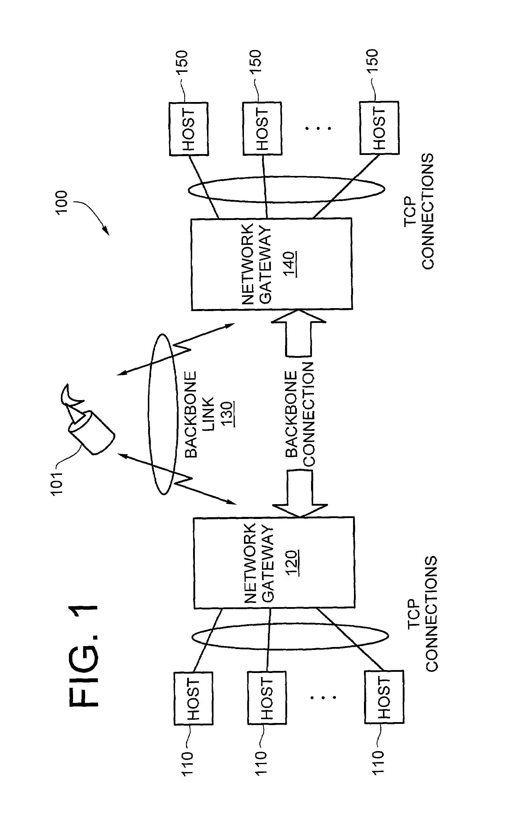
[0055]FIG. 1 illustrates an exemplary network 100 in which the performance enhancing proxy (PEP) of the present invention may be utilized. The network 100 in FIG. 1 includes one or more hosts 110 connected to a network gateway 120 via TCP connections. The network gateway 120 is connected to another network gateway 140 via a backbone connection on a backbone link 130. As seen in FIG....


PUM


Abstract

A communication system having a proxy architecture is disclosed. The system includes a platform that provides performance enhancing functions. The platform includes a backbone connection apparatus that routes information within a communication system. The backbone connection apparatus receives backbone connection parameters from the platform and maintains the current parameters in one or more backbone connection profiles. The backbone connection apparatus routes packets of information throughout the communication system based on the backbone connection profile. The backbone connection apparatus supports the use of different backbone protocol for different types of backbone links. Further, in a configuration where multiple backbone links of different types exist, the backbone connection apparatus supports the use of a different backbone protocol for each type of link at the same time. The above arrangement has particular applicability to a bandwidth constrained communication system, such as a satellite network.

Description

CROSS-REFERENCES TO RELATED APPLICATION[0001]This application is related to and claims the benefit of priority to: (i) U.S. Provisional Patent Application (Ser. No. 60 / 220,026), filed Jul. 21, 2000, entitled “Performance Enhancing Proxy,” and (ii) U.S. Provisional Patent Application (Ser. No. 60 / 225,630), filed Aug. 15, 2000, entitled “Performance Enhancing Proxy”; all of which are incorporated herein by reference in their entirety.FIELD OF THE INVENTION[0002]The present invention is generally directed to a method and system for using a backbone protocol and more particularly, to the backbone protocol which improves network performance.BACKGROUND[0003]The entrenchment of data networking into the routines of modern society, as evidenced by the prevalence of the Internet, particularly the World Wide Web, has placed ever-growing demands on service providers to continually improve network performance. To meet this challenge, service providers have invested heavily in upgrading their net...

Claims


Application Information

Patent Timeline
Patent Type & Authority Patents(United States)
IPC IPC(8): H04Q7/24H04B7/185H04L12/24H04L12/26H04L12/28H04L12/46H04L12/56H04L12/66H04L29/06H04L29/08H04W12/00H04W12/12H04W28/18H04W40/02
CPCH04B7/18582H04L12/2602H04L12/2854H04L12/4604H04L12/5693H04L12/66H04L29/06H04L41/046H04L41/083H04L41/0896H04L41/5022H04L43/00H04L43/0811H04L45/00H04L45/22H04L45/24H04L45/28H04L45/30H04L45/306H04L45/308H04L47/10H04L47/14H04L47/193H04L47/2408H04L47/2433H04L47/2491H04L47/40H04L49/90H04L49/901H04L49/9042H04L49/9094H04L63/1466H04L69/16H04L67/322H04L67/2814H04L67/2833H04L67/327H04L69/22H04L69/161H04L69/163H04L67/2871H04L69/165H04B7/18584H04L69/329H04L29/08846H04L41/06H04L41/0873H04L63/0281H04L63/0428H04W28/18H04W40/02H04L69/18H04L69/14H04L47/50Y02D30/70H04W28/10H04L67/59H04L67/563H04L67/566H04L67/61H04L67/63H04L9/40H04W8/04
Inventor BORDER, JOHNGEE, GREG
Owner HUGHES NETWORK SYST
Why Eureka
Try Eureka