
Method of producing an optical member

a technology of optical components and optical components, applied in glass tempering apparatuses, manufacturing tools, transportation and packaging, etc., can solve the problems of insufficient improvement concerning the distribution of refractive index and birefringence, unsatisfactory effect, and disadvantageous effect on the homogeneity of blanks, and achieve the effect of higher thermal conduction

Inactive Publication Date: 2006-03-07
HERAEUS QUARZGLAS +1
View PDF11 Cites 4 Cited by
  • Summary
  • Abstract
  • Description
  • Claims
  • Application Information

AI Technical Summary

Benefits of technology

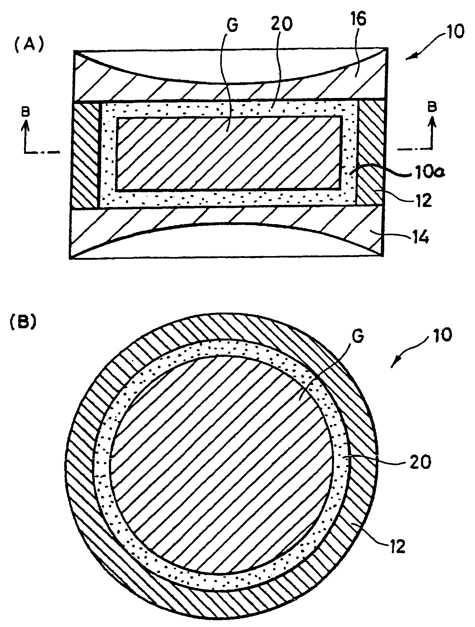
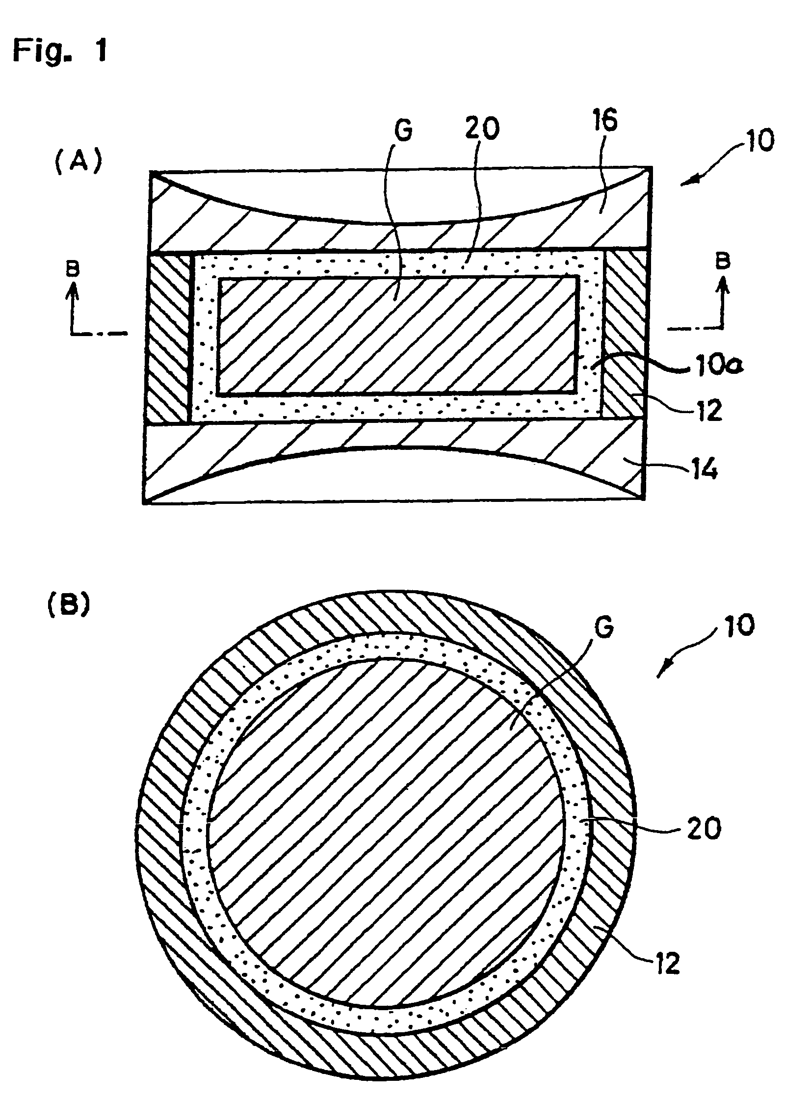
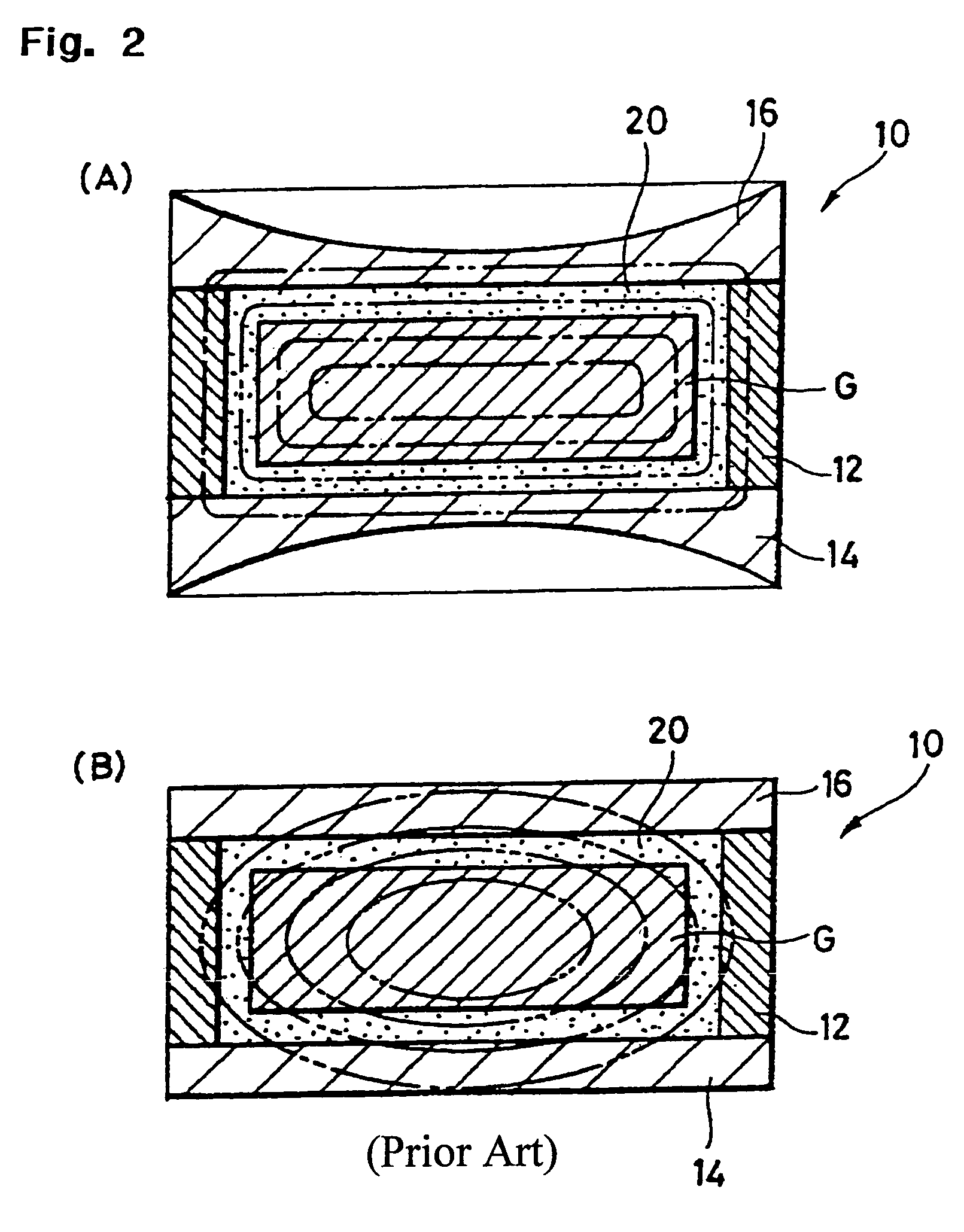
[0039]The cooling rate during annealing of a quartz glass blank is made non uniform by the vessel according to the invention. This shows advantageous effects with respect to the formation of a smaller gradient of the temperature and the hydrogen concentration within the blank and with respect to the distribution of the position of the equilibrium within the contour of the optical member to be produced from it. In this respect reference is made to the above explanations regarding the blank of the invention and the preferred developments thereof.[0040](1) The vessel according to the invention is a vessel for heat-treating a cylindrical blank for an optical member of synthetic quartz glass, which includes the contour of said optical member with an overdimension and comprises an interior for receiving said blank and SiO2 powder for filling intermediate spaces, said interior having a removable upper side and a lower side opposite said upper side and spaced apart therefrom, and an outer edge connecting upper side and lower side and extending around a center axis, characterized in that said upper side and said lower side in the area of said center axis have a higher thermal conduction than in the area of said outer edge.
[0040](1) The vessel according to the invention is a vessel for heat-treating a cylindrical blank for an optical member of synthetic quartz glass, which includes the contour of said optical member with an overdimension and comprises an interior for receiving said blank and SiO2 powder for filling intermediate spaces, said interior having a removable upper side and a lower side opposite said upper side and spaced apart therefrom, and an outer edge connecting upper side and lower side and extending around a center axis, characterized in that said upper side and said lower side in the area of said center axis have a higher thermal conduction than in the area of said outer edge.
[0041]It shows the features according to the following preferred embodiments
[0042](2) The vessel described in (1), wherein lower side and upper side in the area of said outer edge have a larger wall thickness than in the area of said center axis.
[0043](3) The vessel described in (2), wherein upper side and lower side are each equipped with a surrounding thickened portion which begins in the area of said outer edge and extends towards said center axis and in which the wall thickness is greater than in the area of said center axis.
[0044](4) The vessel described in (3), wherein the wall thickness of lower side and upper side decreases continuously across said thickened portion when viewed from said outer edge towards said center axis.

Problems solved by technology

Such a temperature distribution remains as a difference in density even after the completion of the annealing treatment, and this led to an insufficient improvement concerning the distribution in refractive index and the birefringence.
This method can surely improve the distribution in refractive index and the birefringence of a quartz glass to a certain degree, but the effect was found still unsatisfactory.
In this respect a particularly long annealing time of the blank for setting a distribution of the fictive temperature that is as uniform possible may even have a disadvantageous effect on the homogeneity of the blank.
Longer annealing times increase the manufacturing costs, which in turn promotes outdiffusion.
Moreover, a large overdimension entails higher manufacturing costs because of larger losses in material.

Method used


Image

  • Method of producing an optical member
  • Method of producing an optical member
  • Method of producing an optical member

Examples


example 1

[0098]Referring to FIG. 8, there was used a synthetic quartz glass vessel, which comprises a bottom plate 14 and a lid 16 each provided with a concave (spherical) lens shape on one side and having an outer diameter of 250 mm, a maximum thickness of 40 mm and a minimum thickness of 15 mm, and provided with a side wall 5 mm in thickness. A synthetic quartz glass body, i.e., the object of the treatment, was placed at the center of the vessel, and 2.9 kg of powder consisting of particles 63 to 710 μm in size was filled to bury the synthetic quartz glass body. Then, the heat treatment above was applied to the synthetic quartz glass body. More specifically, the synthetic quartz glass body was subjected to heat treatment by placing it in a heat treatment furnace in the state shown in FIG. 8. Thus, the total weight of the synthetic quartz glass powder accounted for 70% of the weight of the synthetic quartz glass body.

example 2

[0099]As shown in FIG. 9, a synthetic quartz glass body was subjected to a heat treatment in a manner similar to Example 1 above except for using a vessel comprising a bottom plate 14 and a lid 16 having a step-wise shape on one side.

example 3

[0100]As shown in FIG. 10, a synthetic quartz glass body was subjected to a heat treatment in a manner similar to Example 1 above except for using a vessel comprising a bottom plate 14 and a lid 16 each provided with slits on one side (at a slit interval of 5 mm for the portion corresponding from the center to a radius of 50 mm, at a slit interval of 10 mm for the portion 50 to 80 mm in radius, at a slit interval of 15 mm for the portion 80 to 110 mm in radius, and no slits for the portion exceeding 110 mm in radius).


PUM

PropertyMeasurementUnit
Thicknessaaaaaaaaaa
Areaaaaaaaaaaa
Distanceaaaaaaaaaa

Abstract

An object of the present invention is to provide an improved blank such that an optical member of a high homogeneity can be obtained therefrom, and to provide a vessel and a heat treatment method for heat-treating a highly uniform synthetic quartz blank. In a first aspect of the invention a special designed blank is provided showing a concave shaped outer surface. In a second aspect of the invention a special designed vessel for heat-treating blanks is provided, whereby the degree of heat emission at the center is set higher than that of the surroundings.

Description

[0001]This application is a divisional of U.S. patent application Ser. No. 09 / 997,222 filed Nov. 28, 2001, by applicants Tetsuji Ueda et al., now abandoned.FIELD OF THE INVENTION[0002]The present invention relates to a blank for an optical member of quartz glass which includes a contour of the optical member with an overdimension and has a surface which is defined by a lower side, an upper side opposite the lower side and spaced apart therefrom and by an outer edge extending around a center axis.[0003]Furthermore, the present invention relates to a vessel for heat-treating a cylindrical blank for an optical member of synthetic quartz glass, which includes the contour of said optical member with an overdimension and comprises an interior for receiving said blank and SiO2 powder for filling intermediate spaces, said interior having a removable upper side and a lower side opposite said upper side and spaced apart therefrom, and an outer edge connecting upper side and lower side and ext...

Claims


Application Information

Patent Timeline
IPC IPC(8): C03C23/00C03B19/14C03B32/00
CPCC03B19/1453C03B32/00C03C23/007Y10T428/131Y10T428/24612
Inventor UEDA, TETSUJIFUJINOKI, AKIRANISHIMURA, HIROYUKITROMMER, MARTINOCHS, STEFAN
Owner HERAEUS QUARZGLAS
Learn More