Liquid dispenser and flexible bag therefor

Inactive Publication Date: 2006-03-07
BAXTER INT INC
View PDF223 Cites 45 Cited by
  • Summary
  • Abstract
  • Description
  • Claims
  • Application Information

AI Technical Summary

Benefits of technology

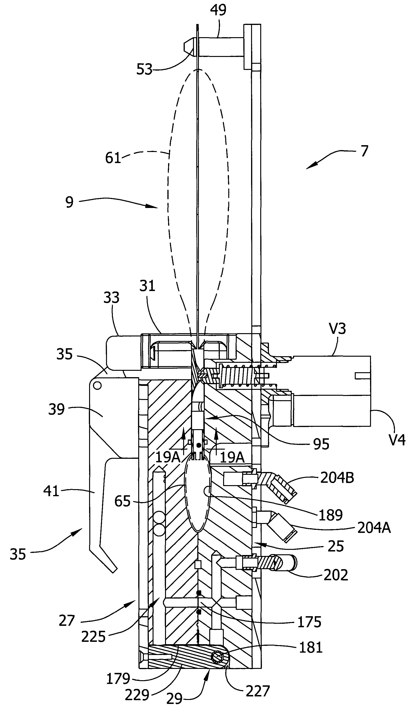
[0009]In still another aspect of the present invention, a flow control apparatus controls the flow of a fluent material containing particulate matter having a known maximum length from a flexible container by acting on the container. The flow control apparatus comprises a shell sized and shaped for receiving at least a portion of the flexible container therein. A valve is disposed for movement relative to the shell between an open position in which fluent material may flow within the flexible container in a direction past the location of the valve and a closed position in which fluent material is bl

Problems solved by technology

The flow rates may produce fluid flow effects which act on the flexible bag in ways which are detrimental to its operation.
For instance, the bag material may tend to collapse under pressure drops caused by rapid fluid flow rates.
If the fluent material is liquid containing particulate matter, the particulate matter can block a valve from reaching a fulling closed position

Method used


Image

  • Liquid dispenser and flexible bag therefor
  • Liquid dispenser and flexible bag therefor
  • Liquid dispenser and flexible bag therefor

Examples


Example

[0088]Before describing another embodiment, the general operation of the first embodiment will be described. Referring first to FIG. 20, a controller 233 (e.g., a programmable logic controller) is connected to the solenoid valves V1–V8 (only two of which are illustrated) to activate and deactivate the valves according to a preset program of operation. The controller 233 is also connected to the control valves PV1–PV4 (not shown in FIG. 21). The control valves PV1–PV4 could be controlled by a separate controller (not shown) without departing from the scope of the present invention. The pneumatic system of the flow control apparatus 7 includes a pump 235 for providing suitable fluid pressures above atmospheric. A line 237 from the pump 235 extends through a control valve 239 and past a pressure sensor 241 to a tank 243. Another line 245 extending from the tank 243 breaks into two branches (245A, 245B), each having its own pressure regulator 247. The branches 245A, 245B are then connec...

Example

[0096]A portion of a flow control apparatus 7′ of a second embodiment is schematically illustrated in FIG. 24. The construction of the flow control apparatus may be essentially identical to the flow control apparatus 7 of the first embodiment except that the pump 235 and control valves PV1–PV4 of the first embodiment are replaced with three cylinders, designated 257, 259 and 261, respectively. The cylinders 257, 259, 261 (and the cylinders of the various versions of the second embodiment) have the advantage of being able to fit in a very small volume and to operate silently. The cylinders 257, 259, 261 are connected in a closed pneumatic loop with a volume acted on by the cylinders. Moreover, the cylinders 257, 259, 261 provide substantially instant operation (i.e., instant application of vacuum and positive pressure) without the provision of a holding or accumulator tank (e.g., tank 243 shown in FIG. 21). Each of the cylinders 257, 259, 261 has a piston head 263 movable lengthwise ...


PUM


Abstract

A liquid dispenser uses a flexible bag having expansible and collapsible cells. A rigid manifold, and in one instance a rigid frame is provided in the bag to keep passages open in use and to isolate one of the cells from the remaining cells. The dispenser employs an efficient and quiet air pressure operating system. In one application, a concentrated drink mix may be held in a reservoir and diluted within other cells in the bag for dispensing to a cup or the like. A valve system allows for the particulates in the liquid without compromising the function of the valve.

Description

CROSS-REFERENCE TO RELATED APPLICATION[0001]This application is a continuation-in-part of U.S. patent application Ser. No. 10 / 351,006, filed Jan. 24, 2003 now abandoned, entitled “LIQUID DISPENSER AND FLEXIBLE BAG THEREFOR,” which is hereby incorporated herein by reference in its entirety for all purposes.BACKGROUND OF THE INVENTION[0002]This invention relates generally to pumps which act on flexible bags to dispense fluent material, and more particularly to a liquid dispenser employing a flexible bag suitable for higher flow rate operation.[0003]Pumps are often used in applications where the surfaces contacting a fluent material being pumped should be kept clean. Such fluent materials include food, beverages, and medicinal products in the form of liquids, powders, slurries, dispersions, particulate solids or other pressure transportable fluidizable material. For instance, where the fluent material is a food additive for a food product, it is imperative that surfaces contacting the ...

Claims


Application Information

Patent Timeline
IPC IPC(8): B65D35/28B65D77/30B67D1/00B67D1/04
CPCB65D77/30B67D1/0037B67D1/0078B67D1/0079B67D1/1286B67D3/041B67D1/0462B65D2231/004B67D2210/0006B67D1/0801B67D2001/0814
Inventor DANBY, HAL C.SCHARF, MICHAEL W.SWAN, JULIAN FRANCIS RALPHBACEHOWSKI, DAVID V.
Owner BAXTER INT INC
Why Eureka
Try Eureka