Micropump assembly for a microgas chromatograph and the like

a technology of microgas chromatograph and micropumps, which is applied in the direction of positive displacement liquid engines, piston pumps, liquid fuel engines, etc., can solve the problems of not meeting the requirements of many microgas chromatographs, the typical performance of these pumps is limited, and the actuation mechanism is limited

Active Publication Date: 2006-03-07
RGT UNIV OF MICHIGAN
View PDF25 Cites 51 Cited by
  • Summary
  • Abstract
  • Description
  • Claims
  • Application Information

AI Technical Summary

Problems solved by technology

However, these actuation mechanisms are limited by the volume displacement of the membrane and require high drive voltages.
Although valve-less micropumps have been proposed, these pumps have significantly lower performance than micropumps using check valves, particularly for gas operation as described in Gerlach, “Pumping Gases by a Silicon Micropump with Dynamic Passive Valves,” Transducers '97, Proc.
Typical performance of these pumps, however, would not meet the requirements of many micro gas chromatographs.
In particular, the maximum flow rate required, which could be as high as 50 ml / min at a pressure rise of a few tens of an atmosphere, cannot be obtained with present designs.
However, power consumption of electrostatically actuated pumps is comparatively low of the order of a few milliwatts, which is consistent with the power requirements of microgas chromatographs.
In order to apply this electrode concept, fabrication of a curved shape becomes the main challenge.
However, the fabrication process for these has typically been too complex.

Method used


Image

  • Micropump assembly for a microgas chromatograph and the like
  • Micropump assembly for a microgas chromatograph and the like
  • Micropump assembly for a microgas chromatograph and the like

Examples


Embodiment Construction

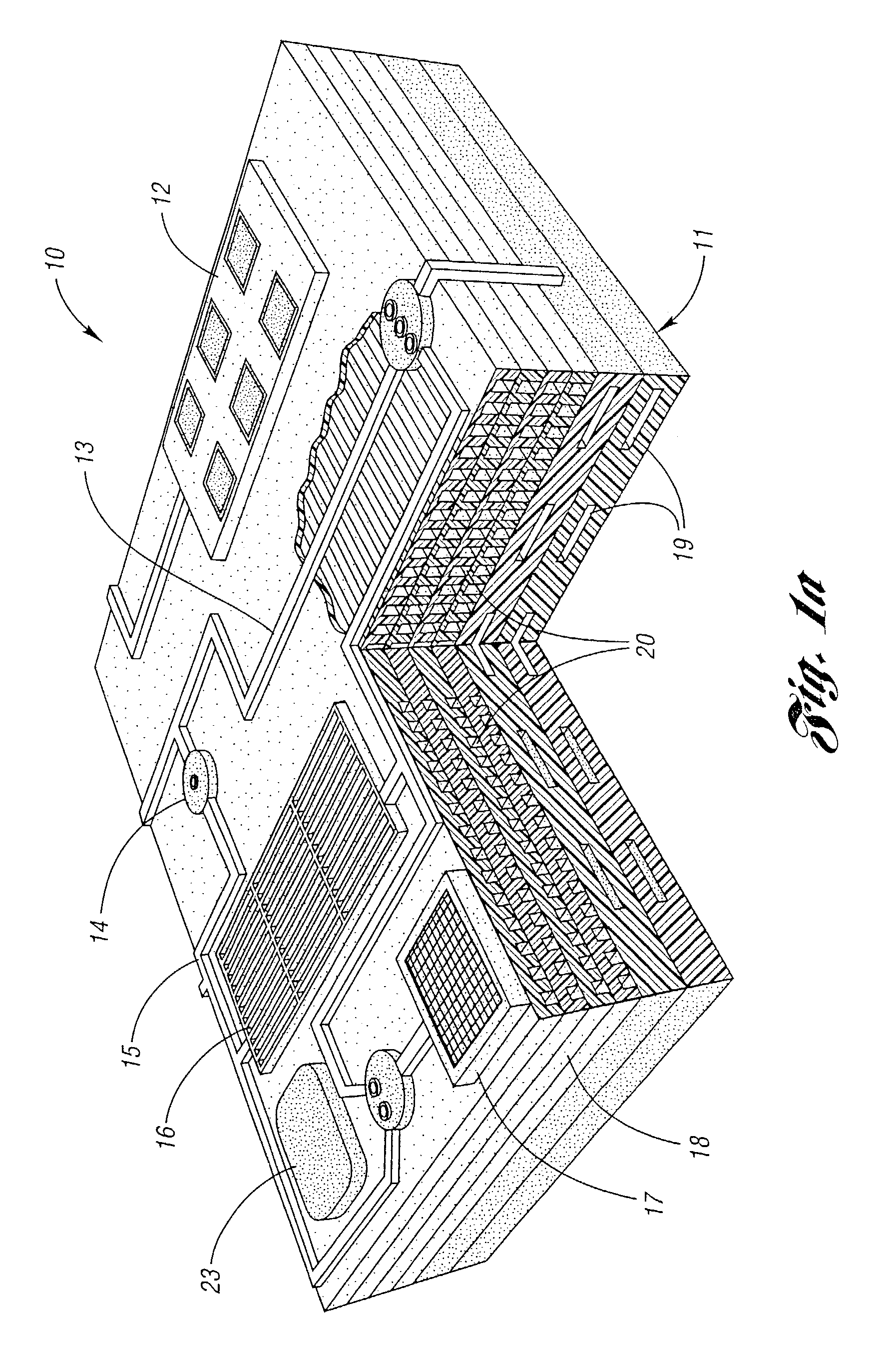
[0060]A pump assembly of the present invention is particularly useful in a microgas chromatograph, generally indicated at 10 in FIG. 1a. The pump assembly is generally indicated at 11. The chromatograph 10 also includes a multi-sensor array 12, sealed channel 13, a latching bypass valve 14, column vias 15, a multistage preconcentrator 16, filtered inlet 17, a calibration source 23 and a stacked DRIE μ-column 18.

[0061]The pump assembly 11 includes pump vias 19 and the μ-Column 18 includes polar / non-polar columns 20.

Pump Assembly Overview

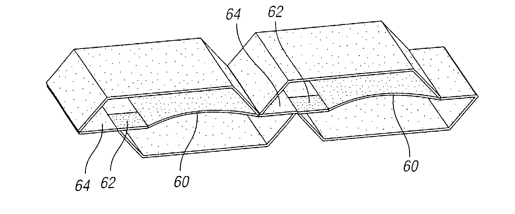
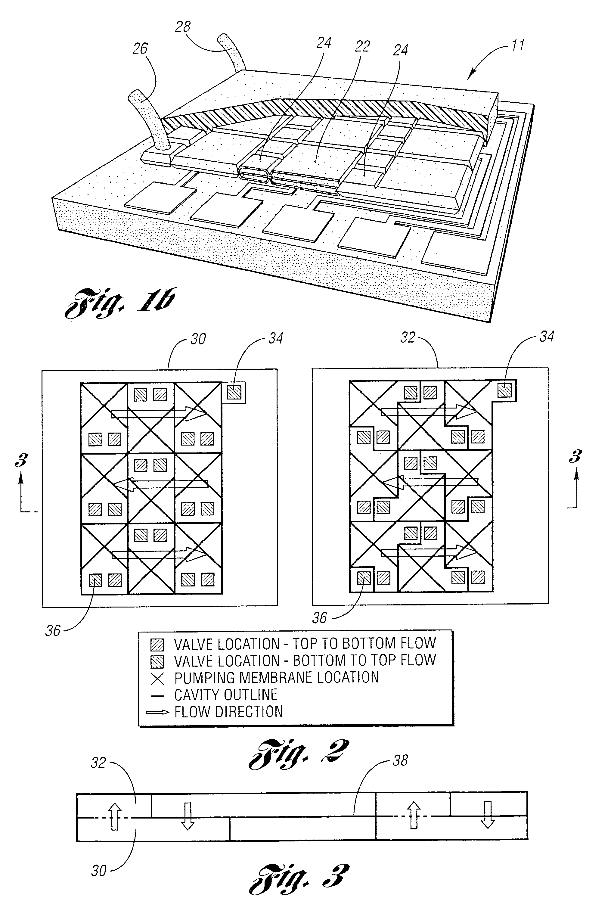
[0062]Referring to FIG. 1b, the assembly of the invention includes a micropump 22 having a series arrangement of micromachined pump cavities, connected by microvalves 24. An inlet tube 26 and an outlet tube 28 are provided. Each cavity has an inlet and outlet valve to allow gas to enter or exit during the appropriate stage of the pump cycle. The pump cavities are stacked on one another in such a way that two cavities can be driven by one pumping membr...


PUM


Abstract

A MEMS-fabricated microvacuum pump assembly is provided. The pump assembly is designed to operate in air and can be easily integrated into MEMS-fabricated microfluidic systems. The pump assembly includes a series of pumping cavities with electrostatically-actuated membranes interconnected by electrostatically-actuated microvalves. A large deflection electrostatic actuator has a curved fixed drive electrode and a flat movable polymer electrode. The curved electrodes are fabricated by buckling the electrode out-of-plane using compressive stress, and the large deflection parallel-plane electrostatic actuators are formed by using the curved electrode. The curved electrode allows the movable electrode to travel over larger distances than is possible using a flat electrode, with lower voltage. The movable electrode is a flat parylene membrane that is placed on top of the curved electrode using a wafer-level transfer and parylene bonding process. Using this approach, large out-of-plane deflection of the parylene membrane is achieved using a voltage smaller than is achievable using flat parallel-plate electrodes.

Description

CROSS-REFERENCE TO RELATED APPLICATION[0001]This application claims the benefit of U.S. provisional application Ser. No. 60 / 380,248, filed May 13, 2002 and entitled “Micro-Pump Concept.”STATEMENT REGARDING FEDERALLY SPONSORED RESEARCH OR DEVELOPMENT[0002]This invention was made with Government support under Award Nos. EEC-9986866 and EEC-0096866. The Government has certain rights in the invention.BACKGROUND OF THE INVENTION[0003]1. Field of the Invention[0004]This invention relates to micropump assemblies for microgas chromatographs and the like.[0005]2. Background Art[0006]In the last decade, a large number of micropump designs have been reported in the literature. Zengerle & Sandmaier provide an overview of early developments of micropumps in 1996 Microfluidics, Proc. Seventh International Symposium on Micro Machine and Human Science, pp. 13–20, IEEE.[0007]Several trends in the design of micropumps are readily identified in the literature. Actuation is a key element of the pump. F...

Claims


Application Information

Patent Timeline
Patent Type & Authority Patents(United States)
IPC IPC(8): F04B25/00F04B17/03F04B43/04F04B45/047
CPCF04B45/047F04B43/043
Inventor NAJAFI, KHALILKIM, HANSEUP S.BERNAL, LUIS P.ASTLE, AARON A.WASHABAUGH, PETER D.
Owner RGT UNIV OF MICHIGAN
Why Eureka
Try Eureka