Piezoelectric element formation member, method of manufacturing the same, piezoelectric actuator unit and liquid ejection head incorporating the same
Active Publication Date: 2006-03-07
SEIKO EPSON CORP
View PDF6 Cites 6 Cited by
Summary
Abstract
Description
Claims
Application Information
AI Technical Summary
This helps you quickly interpret patents by identifying the three key elements:
Problems solved by technology
Method used
Benefits of technology
Benefits of technology
[0014]It is therefore an object of the invention to provide a piezoelectric element formation member advantageous to the downsizing requirement and the yield enhancement, by providing an external electrode at a functionally proper portion to alleviate the tolerance requirement.
[0025]In order to form the above second external electrode layer, a mask having a widened portion corresponding to the narrowed second section is used when the external electrode layers are formed through the vapor deposition. Accordingly, the stiffness of the mask can be secured so that the undesired flexure during the vapor deposition is prevented even if the portion which is not involved with the piezoelectric action is downsized. Further, since the area of the unnecessary part of the second external electrode layer is reduced, it is advantageous to the cost reduction and the downsizing.
[0026]Preferably, the second dimension is substantially zero. In this case, the stiffness of the mask is further enhanced.
[0044]In such a configuration, the vapor deposition can be precisely executed even when a plurality of piezoelectric element formation members are simultaneously manufactured.
Problems solved by technology
These problems may occur not only in ink jet recording heads, but also similarly occur in other liquid ejection heads for ejecting liquid other than ink.
Method used
Image
Click on the blue label to locate the original text in one second.
Reading with bidirectional positioning of images and text.
Examples
first embodiment
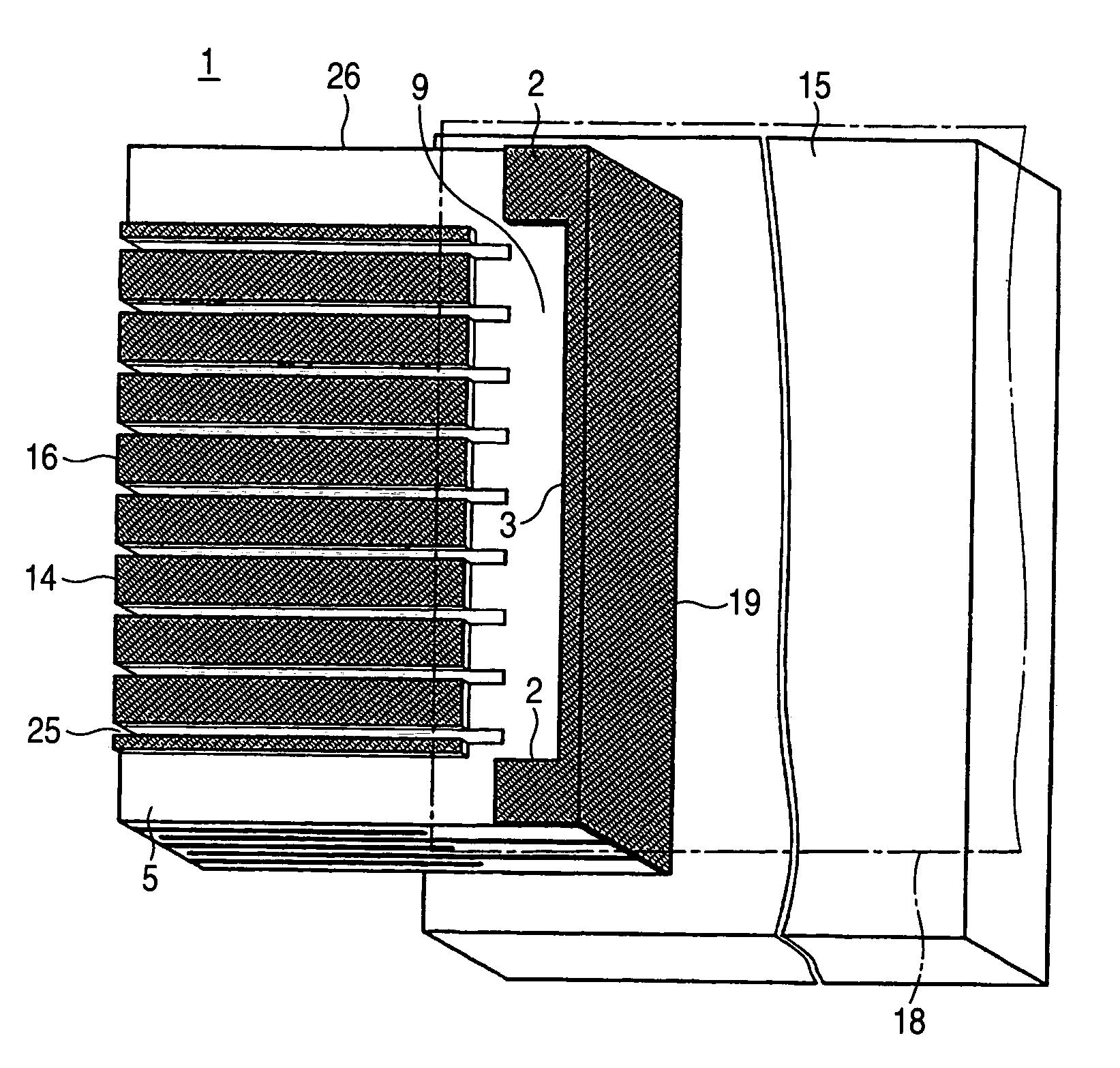
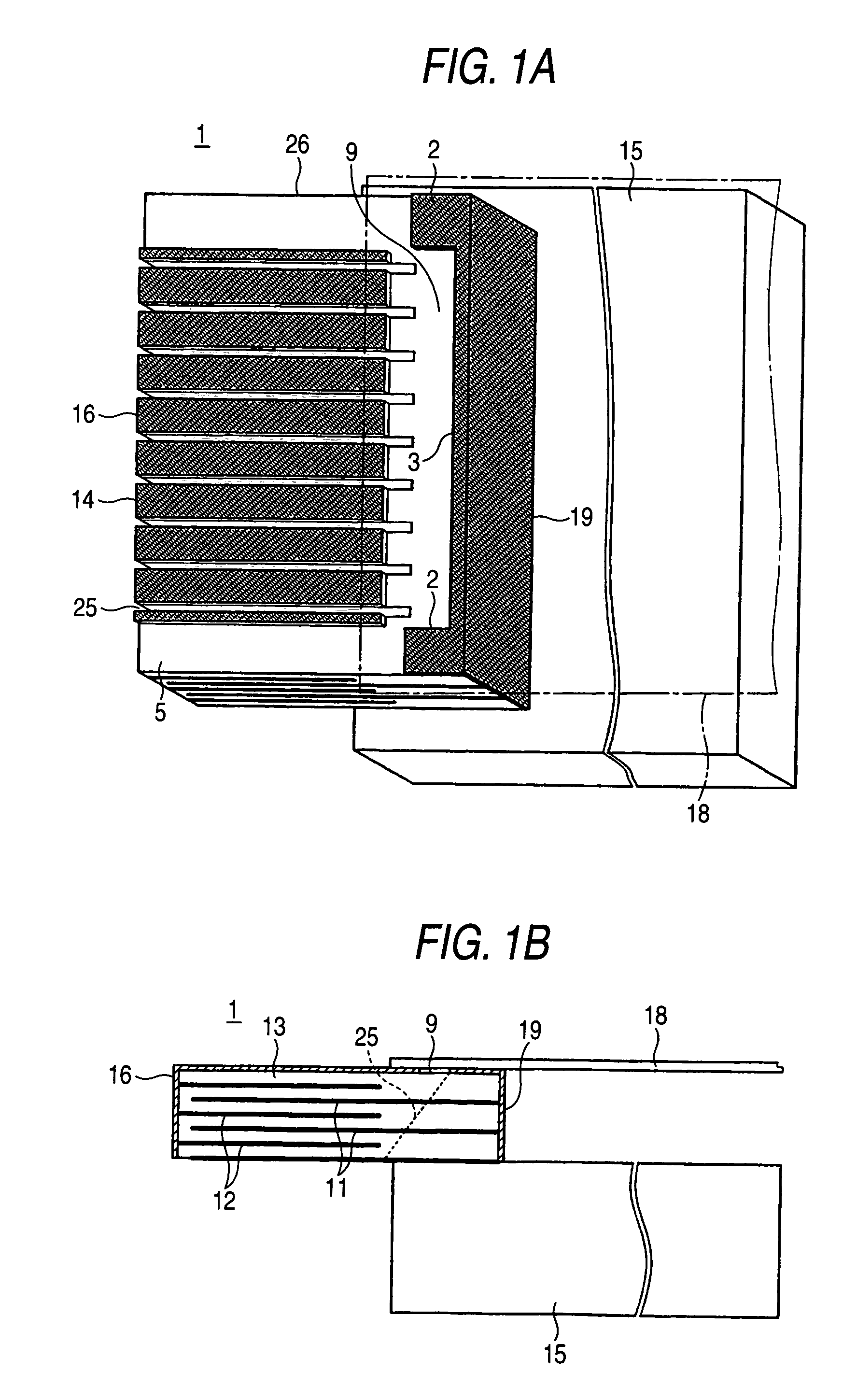
[0067]As shown in FIGS. 1A and 1B, a piezoelectric actuator unit 1 according to the invention comprises a piezoelectric element formation member 23 and a fixation board for supporting the piezoelectric element formation member 23 thereon in a cantilevered manner. This piezoelectric actuator unit 1 is assembled in a liquid ejection head such as an ink jet recording head.
[0068]The piezoelectric element formation member 23 is formed by alternately laminating internal electrodes serving as two poles in a piezoelectric element 14 with piezoelectric material layers 13. Specifically, internal segment electrodes 12 to be segment electrodes each of which is electrically independent from an adjacent piezoelectric actuator, and internal common electrodes 11 to be a common electrode which is common to the respective piezoelectric actuators are alternately laminated while sandwiching the piezoelectric material layers 13 therebetween.
[0069]A plurality of slits 25 are formed in the piezoelectric e...
second embodiment
[0096]FIG. 5 shows a piezoelectric actuator unit according to the present invention.
[0097]In this embodiment, the band section 7 of the mask 4 is formed with a protruded portion 6 which extends to the rear end of the piezoelectric element formation member 23. Accordingly, the narrowed portion 3 of the external common electrode 19 is formed as a region which is provided on the rear end face of the piezoelectric element formation member 23, but is not provided on the top face thereof.
[0098]In such a configuration, the stiffness of the band section 7 is further enhanced, while further reducing the area of the unnecessary part of the external common electrode 19.
third embodiment
[0099]FIG. 6 shows a piezoelectric actuator unit according to the present invention.
[0100]In this embodiment, the widened portions 2 and the narrowed portion 3 are connected via portions 41 at which the width of the external common electrode 19 in the longitudinal direction of the piezoelectric element 14 is gradually varied. FIG. 6 show an example that the width at the portion 41 is linearly varied. However, the portion 41 may have a curved edge.
[0101]In this embodiment, the largest interval between the widened portions 2 in the arrayed direction of the piezoelectric elements 14 is made larger than the dimension of the region where the external segment electrodes 16 are formed in the arrayed direction of the piezoelectric elements 14.
[0102]In such a configuration, the area of the contact portions of the external common electrode 19 with respect to the flexible cable 18 can be enlarged, so that the tolerance requirement for parts of the mask 4 for forming the contact portions can be...
PUM
Abstract
First internal electrodelayers and second internal electrodelayers are alternately laminated in a substrate while sandwiching piezoelectric material layer therebetween. The first internal electrodelayers are exposed to a first end face of the substrate, and the second internal electrode layers are exposed to a second end face of the substrate which is opposite to the first end face. A first external electrode layer is formed on the first end face and a third end face connecting the first end face and the second end face. A second external electrode layer is formed on the second end face and the third end face. The second external electrode layer is electrically independent from the first external electrode layer. The first external electrode layer and the first internal electrode layers are to be divided by slits extending from the first end face to form a plurality of piezoelectric elements arrayed in a first direction. The second external electrode layer includes a pair of first sections provided on both end portions of the third end face in the first direction, and having a first dimension in a second direction perpendicular to the first direction, and a second section provided between the first sections, and having a second dimension in the second direction which is less than the first dimension.
Description
BACKGROUND OF THE INVENTION[0001]The present invention relates to a piezoelectric element formation member comprising piezoelectric material layer which are deformable in accordance with the application of voltages, and a method of manufacturing such a piezoelectric element formation member. The present invention also relates to a piezoelectric actuator unit in which piezoelectric elements are arrayed and integrated with each other. The present invention also relates to a liquid ejection head incorporating such a piezoelectric actuator unit. For example, the present invention is directed to an ink jet recording head in which pressure fluctuation is caused to ink in pressure generating chambers by the piezoelectric elements to eject ink droplets from nozzle orifices.[0002]It is known an ink jet recording head comprising a piezoelectric actuator unit of longitudinal vibration mode, wherein the piezoelectric elements are extended or shrunk in the axial direction thereof. In such a reco...
Claims
Application Information
Patent Timeline
Application Date:The date an application was filed.
Publication Date:The date a patent or application was officially published.
First Publication Date:The earliest publication date of a patent with the same application number.
Issue Date:Publication date of the patent grant document.
PCT Entry Date:The Entry date of PCT National Phase.
Estimated Expiry Date:The statutory expiry date of a patent right according to the Patent Law, and it is the longest term of protection that the patent right can achieve without the termination of the patent right due to other reasons(Term extension factor has been taken into account ).
Invalid Date:Actual expiry date is based on effective date or publication date of legal transaction data of invalid patent.

