
Arc fault detector and method

a technology of arc fault and detector, which is applied in the field of electrical circuit protection, can solve the problems of arc fault, severe damage, hot unplugging, etc., and achieve the effects of reducing the impact of costly microprocessors, reducing the number of arc faults, and eliminating or minimizing the impact of nuisance tripping of circuit interrupters

Inactive Publication Date: 2006-03-07
DELPHI TECH INC
View PDF9 Cites 52 Cited by
  • Summary
  • Abstract
  • Description
  • Claims
  • Application Information

AI Technical Summary

Benefits of technology

[0009]The methods and apparatus of the present invention address many of the shortcomings of the prior art. The present invention provides systems and methods for detecting an arc fault. In an exemplary embodiment, the instant invention detects a change in current that is indicative of an arc fault. In an exemplary embodiment of the invention, a system distinguishes an arc fault from a slow current transient that may be caused by a load variation or a low-frequency commutation ripple current such as that which might be associated with a DC motor under normal operating conditions. An exemplary embodiment of the invention includes a switch transient detector that detects voltage differential across a load switch and generates a switch transient signal that may be used to prevent a trip signal from being generated. Accordingly, this embodiment may eliminate or minimize the impact of nuisance tripping of a circuit interrupter, helping to enable, where appropriate, the elimination of costly microprocessors and complex algorithms to distinguish switch transients.

Problems solved by technology

Such an arc is often undesirable, its effects may not have been considered, and no provision may have been made to enable its extinction.
In many cases, severe damage may occur if such an arc is sustained.
Hot unplugs that may be caused by loose connections are often series arc faults.
Unfortunately, however, series arc faults cannot typically be cleared by fuses or circuit breakers.
An example of parallel arc faults can be damaged wires drawing an arc to a ground potential, such as a chassis of an automobile.
In an electrical system, the insulation jacket of one or more wires might become broken due to aging, mishandling, or damage (e.g., shaved, chaffed or pinched cable jackets).
In such cases, an arc fault may be created, causing a temporary short circuit.
The arc fault current, however, may thermally over-load and damage contacts within the circuit due to low contact force, resulting in melting and evaporating contact material, which may be followed by still more arcing.
For example, where an electrical system is to be exposed to an extremely volatile substance, such as within a fuel tank of an aircraft or other vehicle, electrical arcing may be extremely serious, and must be mitigated—regardless of the voltage potential of the system.

Method used


Image

  • Arc fault detector and method
  • Arc fault detector and method
  • Arc fault detector and method

Examples


Embodiment Construction

[0028]As discussed above, the methods and systems of the present invention provide improved arc fault detection capable of detecting series and parallel arcs in a DC circuit using low cost electronics, enabling the avoidance, where appropriate, of microprocessors or sophisticated algorithms.

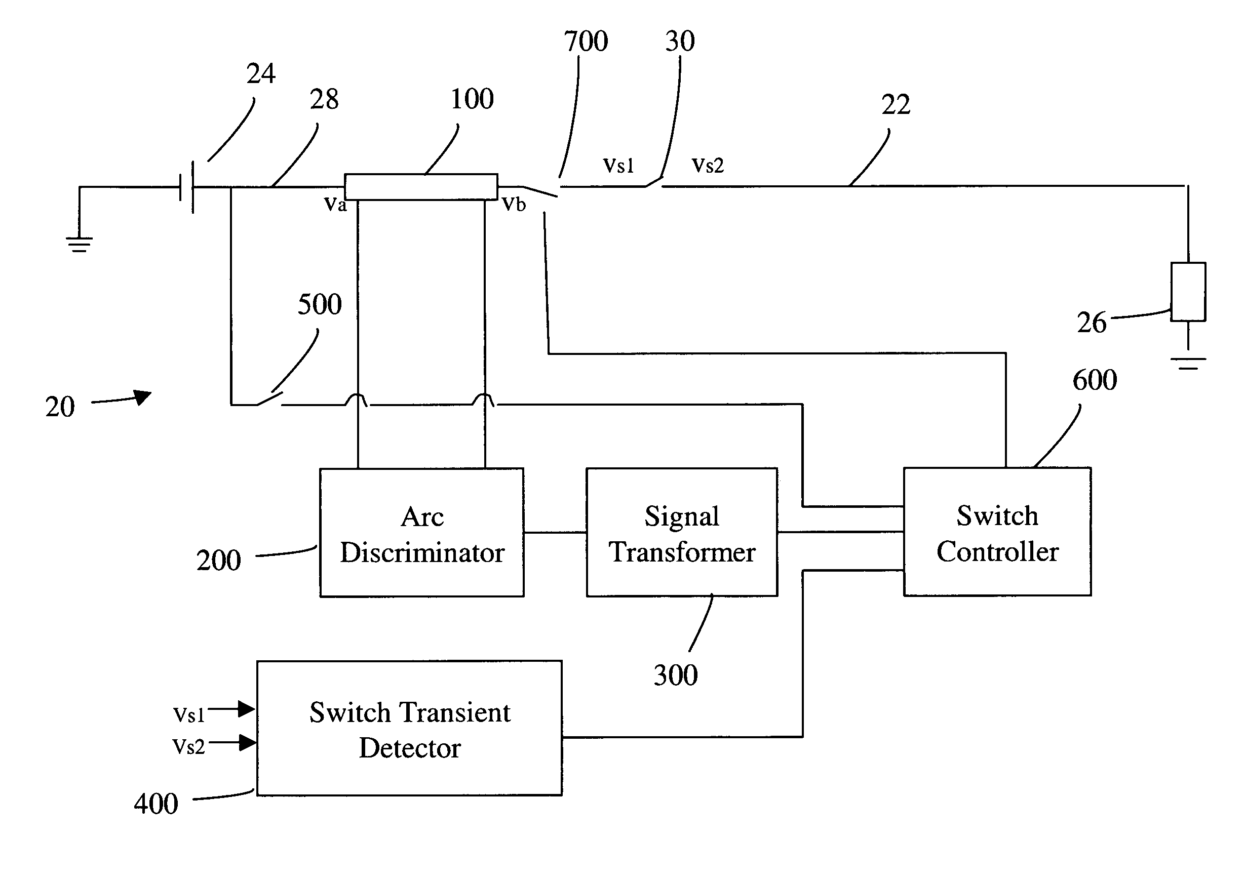
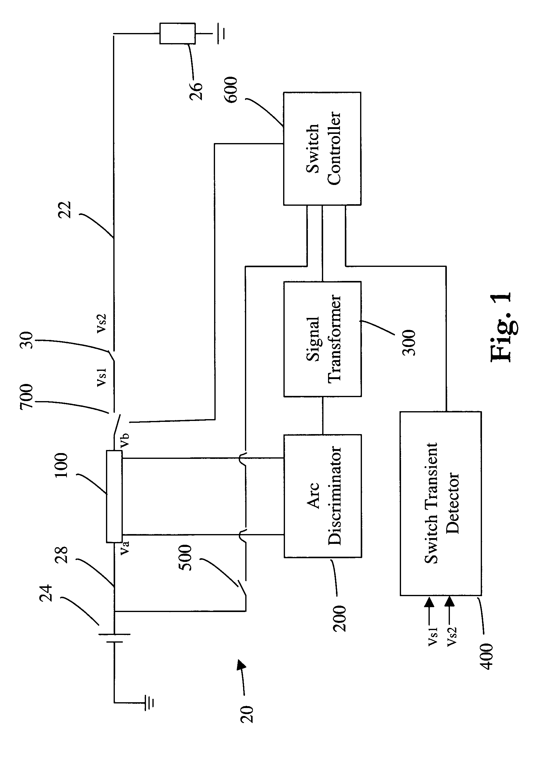
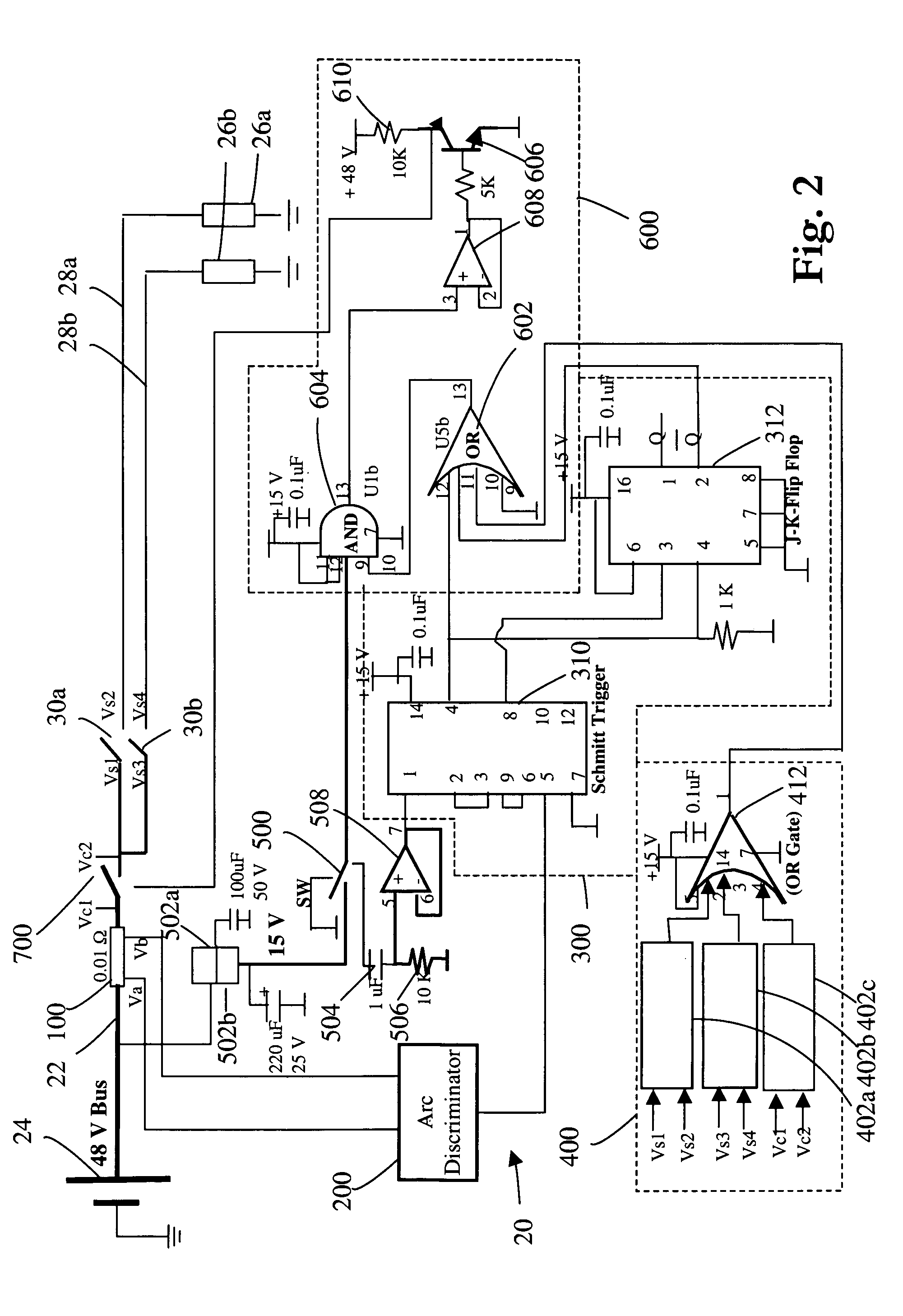
[0029]Referring first to FIGS. 1–4, FIG. 1 is a simplified diagram illustrating a first exemplary embodiment of an arc fault detector 20 of the present invention. As shown in FIG. 1, arc fault detector 20 provides protection to circuit 22. Circuit 22 includes direct current power source or battery 24 providing power to load 26 via conductor 28. Load switch 30 is disposed in conductor 28.

[0030]Arc fault detector 20 includes current shunt resistor 100, arc discriminator 200, signal transformer (i.e., an arc fault signal generator) 300, switch transient detector 400, manual switch 500, switch controller 600, and line interrupter 700.

[0031]Current shunt resistor 100 is coupled to circuit 22 in series...


PUM


Abstract

The present invention discloses an arc fault detector including a shunt resistor deployed in a circuit being protected, an arc discriminator sensing voltages across the shunt resistor and outputting an arc detection signal when it detects current variations caused by parallel and series arc faults, a signal transformer buffering the arc detection signal and outputting a pulse, a switch transient detector detecting a voltage differential across load switches and outputting a pulsed switch transient detection signal when the voltage differential across load switches exceeds a reference value, a line interrupter such as a static relay, a switch controller including logic gates generating a trip signal based on predetermined criteria, and a manual switch for resetting the line interrupter. A second embodiment of the present invention senses voltage induced in a coil wrapped around a toroidal core to detect current variations in conductors which pass through the center of the toroidal core.

Description

PRIORITY[0001]This application claims benefit of priority from U.S. provisional patent application Ser. No. 60 / 465,061, filed Apr. 24, 2003, which is hereby incorporated by reference.TECHNICAL FIELD[0002]The present invention relates generally to the protection of electrical circuits, and, more specifically to systems and methods for detecting and preventing electrical arcing in series and parallel electrical circuits.BACKGROUND OF THE INVENTION[0003]In many electrical systems, a need may arise to increase the voltage potential applied to elements within the system. This need may arise for many reasons including, for example, power source considerations, load considerations, and power transmission considerations. For example, in the automotive industry, need currently exists to increase the electrical power capability for future vehicles caused by design considerations associated with reducing fuel consumption and the introduction of new and / or improved electrical features and devic...

Claims


Application Information

Patent Timeline
IPC IPC(8): G01R31/12G01R31/02H02H1/00H02H3/44
CPCG01R31/025H02H1/0015H02H3/44G01R31/52
Inventor NAIDU, MALAKONDAIAHSCHOEPF, THOMAS J.GOPALAKRISHNAN, SURESH
Owner DELPHI TECH INC
Features
  • Generate Ideas
  • Intellectual Property
  • Life Sciences
  • Materials
  • Tech Scout
  • Unparalleled Data Quality
  • Higher Quality Content
  • 60% Fewer Hallucinations
Learn More