Check patentability & draft patents in minutes with Patsnap Eureka AI!

Linear multiplier circuit

a multiplier circuit and linear technology, applied in the field of multiplier circuits, can solve the problems of difficult and expensive improvement of the poor linearity of analog multipliers, and inability to achieve linear improvements, etc., to achieve the effect of improving the linearity of the multiplier circui

Active Publication Date: 2006-03-07
VIA TECH INC
View PDF2 Cites 3 Cited by
  • Summary
  • Abstract
  • Description
  • Claims
  • Application Information

AI Technical Summary

Benefits of technology

The solution significantly improves linearity by eliminating nonlinear factors, resulting in a multiplier circuit with a linear relationship between input and output signals, reducing power consumption and chip area while maintaining efficient operation.

Problems solved by technology

However, analog multiplier circuits have a disadvantage in that they exhibit poor linearity.
Improvements on the linearity of analog multipliers are difficult and expensive to achieve, particularly where the multipliers are solid-state multipliers such as those implemented in CMOS technology.
This typically results in considerable cost over an analog implementation in the form of A / D and D / A converters and in general with a larger power consumption and chip area than those of an analog implementation.

Method used


Image

  • Linear multiplier circuit
  • Linear multiplier circuit

Examples


Embodiment Construction

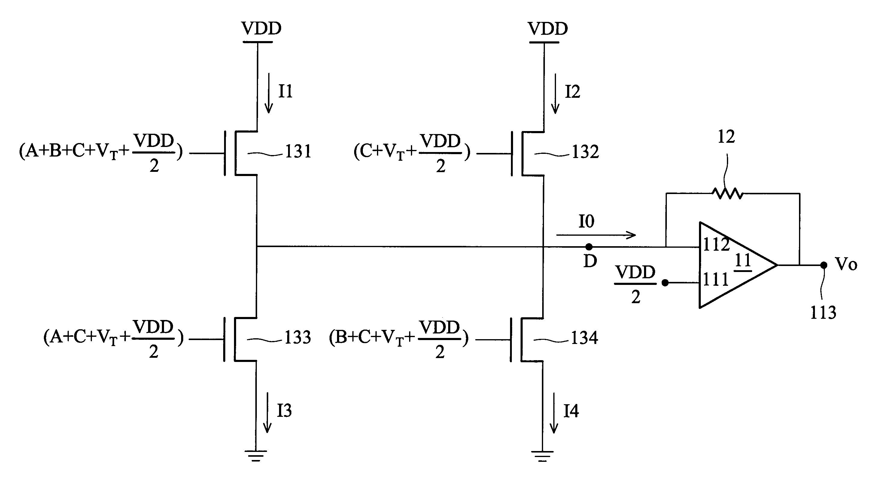
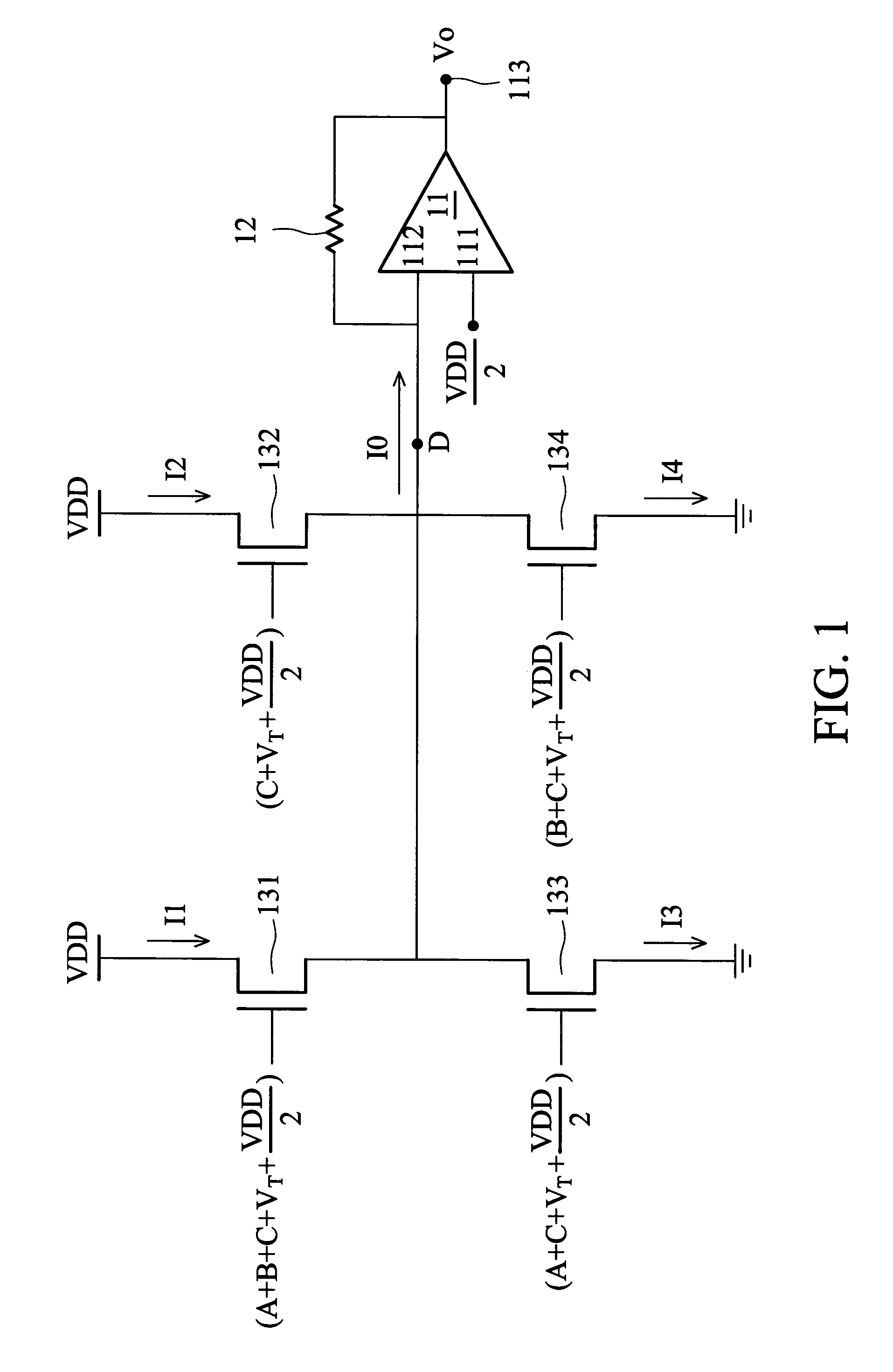
[0014]As shown in FIG. 1, a linear multiplier circuit 1 comprises an operation amplifier 11, a resistor 12, and four transistors 131, 132, 133 and 134, wherein these four transistors substantially have an identity threshold voltage VT. The operation amplifier 11 has a first input terminal 111, a second input terminal 112 and an output terminal 113, wherein the first input terminal is configured for receiving a first voltage potential VDD / 2. The resistor 12 is coupled between the second input terminal 112 and the output terminal 113 of the operation amplifier 11. The transistor 131 has a drain configured for receiving the second voltage potential VDD, a source coupled to the second input terminal 112 of the operation amplifier 11, and a gate used for receiving the sum of two input signals A and B, and an additionally introduced input signal C. The transistor 132 has a drain configured for receiving the second voltage potential VDD, a source coupled to the second input terminal 112 of...


PUM


Abstract

A linear multiplier circuit comprises a first, a second, a third and a fourth transistor, each having a drain, a source, a gate and substantially an identity threshold voltage. Each of these four transistors operates with a fixed drain-to-source voltage applied between the drain and source, a gate-to-source voltage applied between the gate and source. The sources of the first and second transistors, and the drains of the third and fourth transistors are coupled to form the output terminal. The gate-to-source voltages of the first, second, third and fourth transistor are respectively the sum of the first and second input signals, an additionally introduced input signal, and the identity threshold voltage; the sum of the additionally introduced input signal and the identity threshold voltage; the sum of the first input signal, the additionally introduced input signal and the identity threshold voltage; and the sum of the second input signal, the additionally introduced input signal and the identity threshold voltage.

Description

BACKGROUND OF THE INVENTION[0001]1. Field of the Invention[0002]The present invention relates to a multiplier circuit, particularly to a linear multiplier circuit which has a better linearity between its input and output signals.[0003]2. Description of the Prior Art[0004]An analog multiplier is a circuit that can receive two input signals in analog form and generate an output signal proportional in magnitude to the product of the two input signals. The input signals are typically voltages, in which case the analog multiplier is customarily referred to as a voltage-mode analog multiplier. An analog multiplier can be organized either as a two-quadrant or a four-quadrant circuit. The product signal output by the analog multiplier circuit may be converted into a digital format by means of an analog-to-digital (A / D) output stage.[0005]Analog multipliers are used in many different applications, such as modulators, phase comparators, adaptive filters, AC-to-DC converters, and sine / cosine s...

Claims


Application Information

Patent Timeline
Patent Type & Authority Patents(United States)
IPC IPC(8): G06F7/44G06G7/16
CPCG06G7/16
Inventor CHU, WEI-SHANG
Owner VIA TECH INC
Features
  • R&D
  • Intellectual Property
  • Life Sciences
  • Materials
  • Tech Scout
  • Unparalleled Data Quality
  • Higher Quality Content
  • 60% Fewer Hallucinations
Learn More