Method and circuit for fuse programming and endpoint detection

a programmable fuse and programming method technology, applied in the field of electrical circuits, can solve the problems of agglomeration, melting, and melting of the silicium top layer, and achieve the effect of preventing damage to the fuse and the surrounding structure, increasing resistance, and increasing the resistan

Active Publication Date: 2006-03-07
MICROCHIP TECH INC
View PDF17 Cites 31 Cited by
  • Summary
  • Abstract
  • Description
  • Claims
  • Application Information

AI Technical Summary

Benefits of technology

[0011]Programming a silicide fuse may cause the silicide top layer to heat up and eventually melt and agglomerate with the underlying polysilicon fuse body. After programming, the silicide fuse has an increased resistance; therefore, the programmed state of the fuse may be determined by monitoring the electrical characteristics (e.g., a voltage) associated with the fuse. Damage to the fuse and the surrounding structures may be prevented by stopping the programming of a particular fuse when a specific electrical characteristic associated with the fuse is detected. Also, faster programming of a plurality of fuses may be achieved by simultaneously providing a logic signal that indicates the programmed state of the fuse.

Problems solved by technology

Programming a silicide fuse may cause the silicide top layer to heat up and eventually melt and agglomerate with the underlying polysilicon fuse body.

Method used


Image

  • Method and circuit for fuse programming and endpoint detection
  • Method and circuit for fuse programming and endpoint detection
  • Method and circuit for fuse programming and endpoint detection

Examples


Embodiment Construction

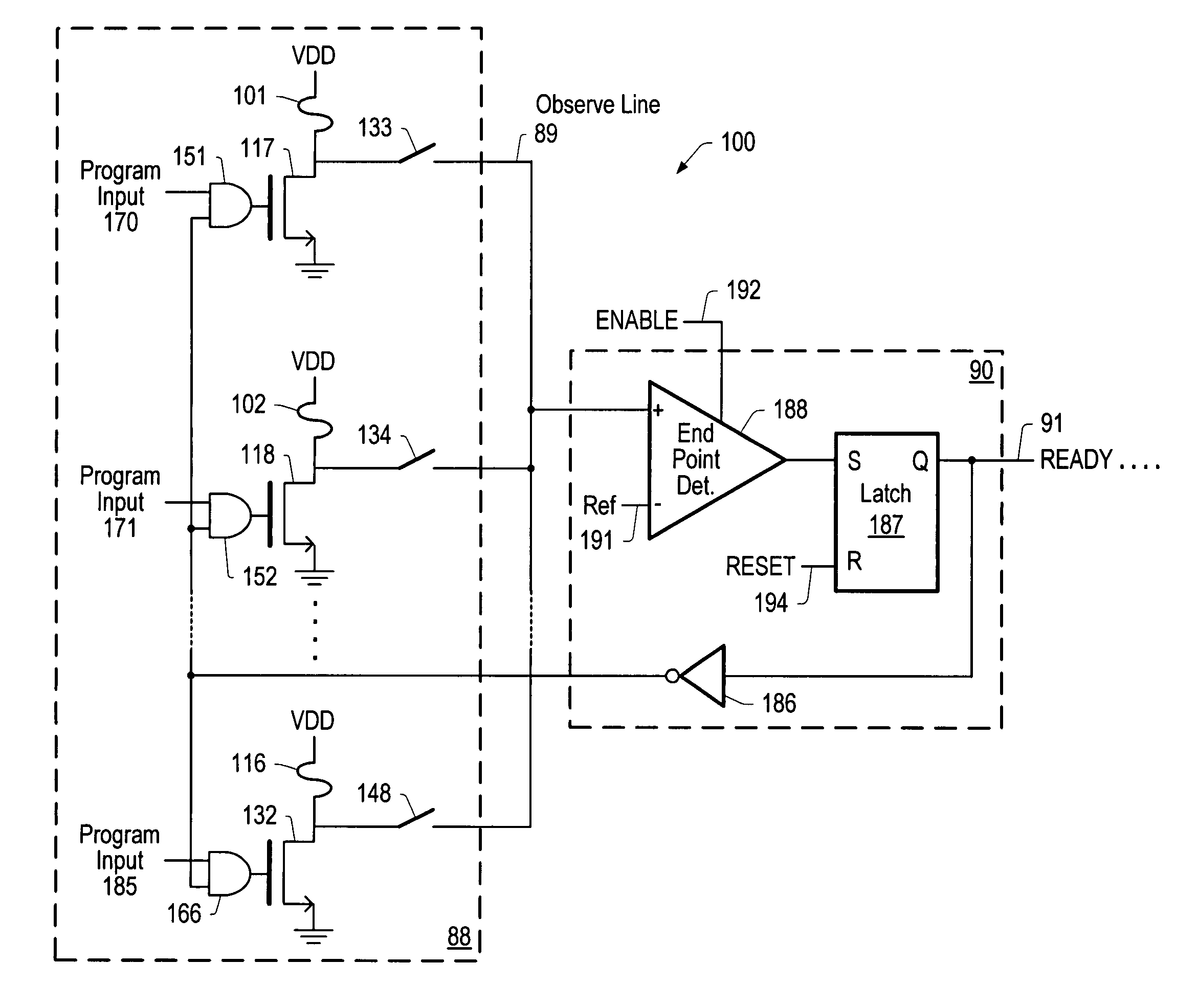
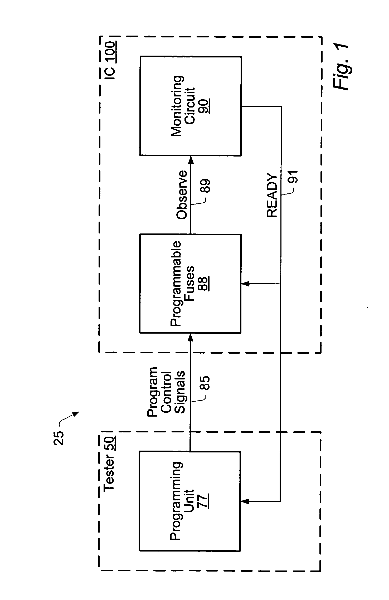
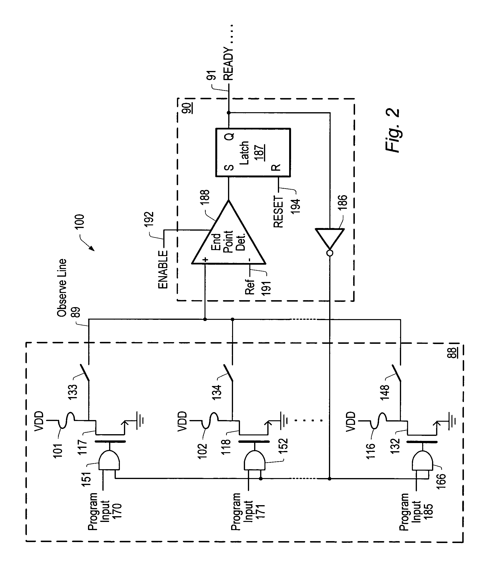
[0018]Turning now to FIG. 1, a block diagram of one embodiment of a system 25 for programming fuses is shown. System 25 may comprise a tester 50, which is coupled to an IC 100 for testing and trimming the IC 100. The tester 50 may comprise a programming unit 77, and the IC 100 may comprise a plurality of programmable fuses 88 and a monitoring circuit 90. It is noted that the programmable fuses 88 and the monitoring circuit 90 may be comprised in any type of integrated circuit, for example, a mixed-signal integrated circuit. It is also noted that in other embodiments the programmable fuses 88 and the monitoring circuit 90 may be comprised in separate integrated circuits.

[0019]In one embodiment, programming unit 77 may be operable to program one or more of the plurality of programmable fuses 88 to trim or calibrate the IC 100. System 25 may further comprise a monitoring circuit 90, which may be operable to monitor electrical characteristics associated with a programmable fuse while th...


PUM


Abstract

In one embodiment, a system comprises a programming unit coupled to at least one programmable fuse and configured to program the programmable fuse. In addition, the system comprises a monitoring circuit coupled to the programmable fuse and configured to monitor electrical characteristics associated with the programmable fuse while the programmable fuse is being programmed. In one embodiment, the monitoring circuit is configured to detect a voltage associated with the programmable fuse. Furthermore, the monitoring circuit is configured to compare the detected voltage associated with the programmable fuse with a predetermined voltage value (i.e., endpoint detection). If the detected voltage is equal to or less than the predetermined voltage value, the monitoring circuit is configured to change a state of a control signal to stop the programming of the programmable fuse. Otherwise, the programming unit continues to program the programmable fuse.

Description

BACKGROUND OF THE INVENTION[0001]1. Field of the Invention[0002]This invention relates to electronic circuits and, more particularly, to programming non-volatile programmable fuses and endpoint detection.[0003]2. Description of the Related Art[0004]Mixed-signal and analog integrated circuits (ICs) may require post-fabrication trimming or calibration to center reference voltages, set oscillator frequency, or adjust other critical parameters within the chip to conform to specifications and meet customer requirements. Several methods exist for trimming ICs, such as programming metal or polysilicon fuses, zapping zener diodes, or programming EPROMs and EEPROMs.[0005]Fuses are two-terminal devices that may be used for trimming ICs. Usually when unprogrammed, a fuse is a low resistive element; but the fuse becomes a high resistive element after “blowing” or programming the fuse to trim a particular IC. In some cases, programming a fuse results in an open circuit. Fuses are typically non-v...

Claims


Application Information

Patent Timeline
Patent Type & Authority Patents(United States)
IPC IPC(8): H01H85/00G11C17/16G11C17/18H01H37/76
CPCG11C17/18G11C17/16
Inventor ILLEGEMS, PAUL F.
Owner MICROCHIP TECH INC
Why Eureka
Try Eureka