System and method for high numeric aperture imaging systems

a technology of numeric aperture and imaging system, applied in the field of imaging systems, can solve the problems of low-light, high-resolution imaging, small depth of field in which to view target objects, loss of spatial resolution and decrease of signal-to-noise ratio associated with the image of target objects

a technology of numeric aperture and imaging system, applied in the field of imaging systems, can solve the problems of low-light, high-resolution imaging, small depth of field in which to view target objects, loss of spatial resolution and decrease of signal-to-noise ratio associated with the image of target objects

US7009651B2Inactive Publication Date: 2006-03-07CYTEK BIOSCI

Image

  • System and method for high numeric aperture imaging systems
  • System and method for high numeric aperture imaging systems
  • System and method for high numeric aperture imaging systems

Examples


Embodiment Construction

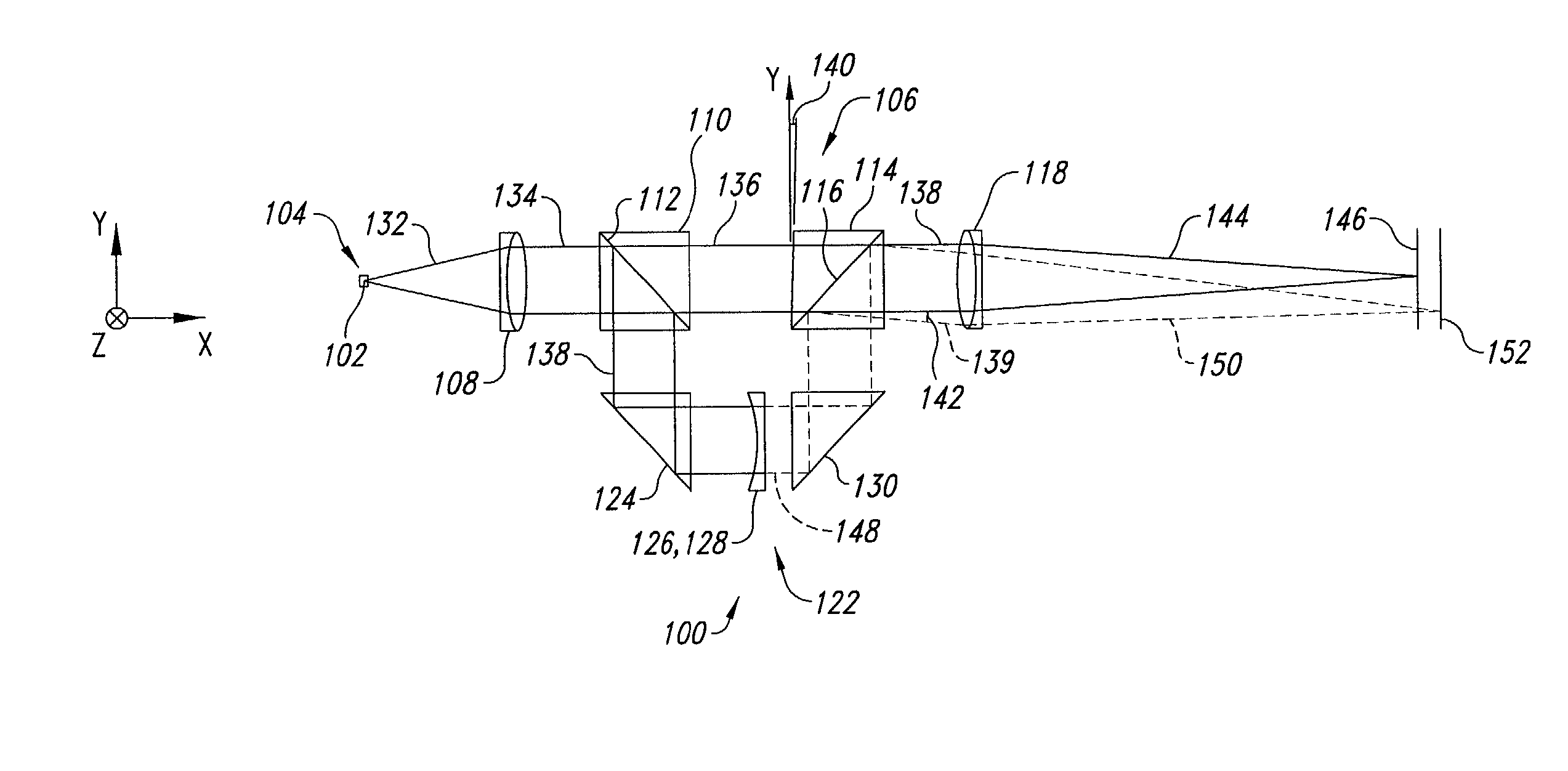
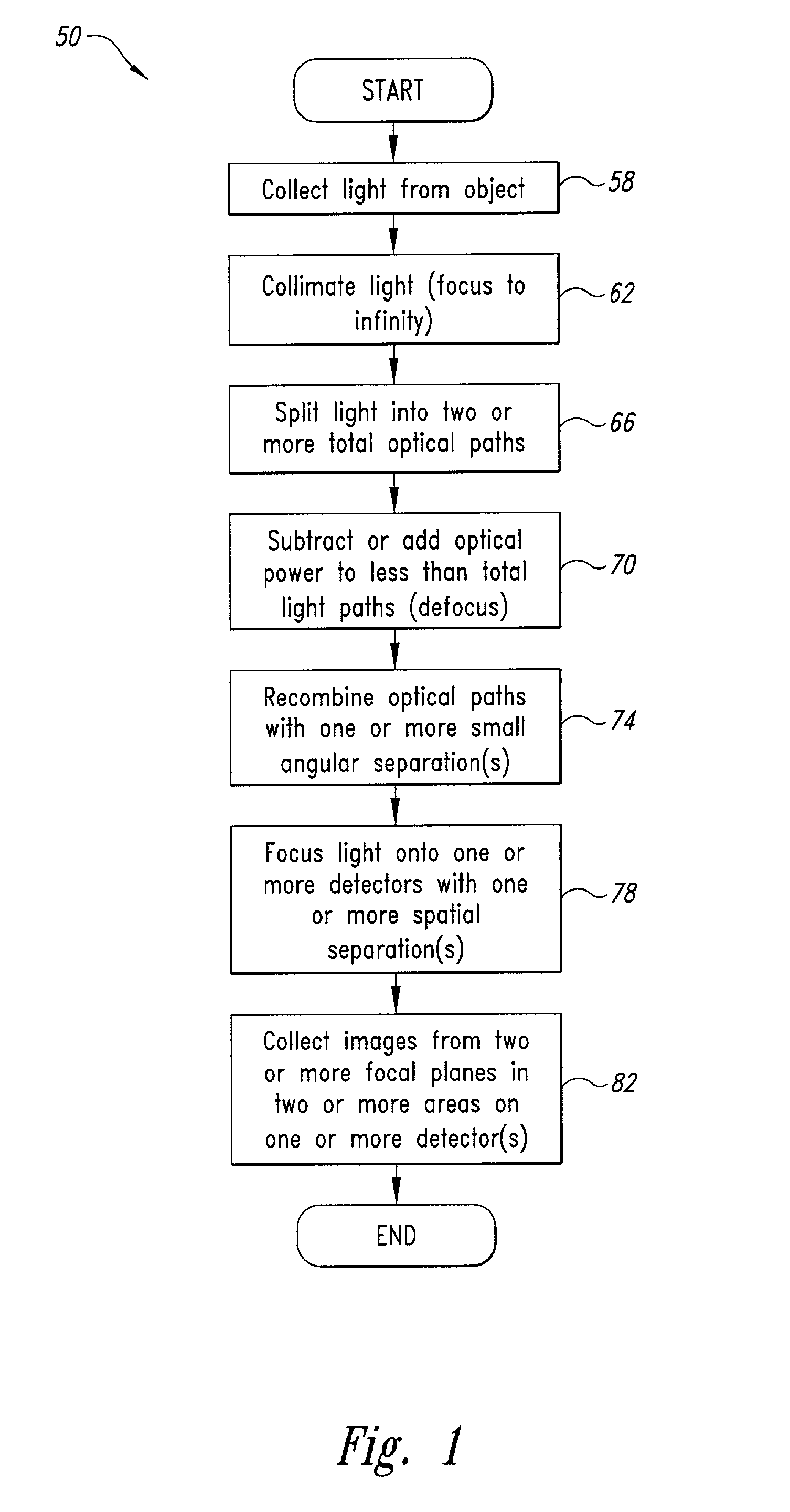
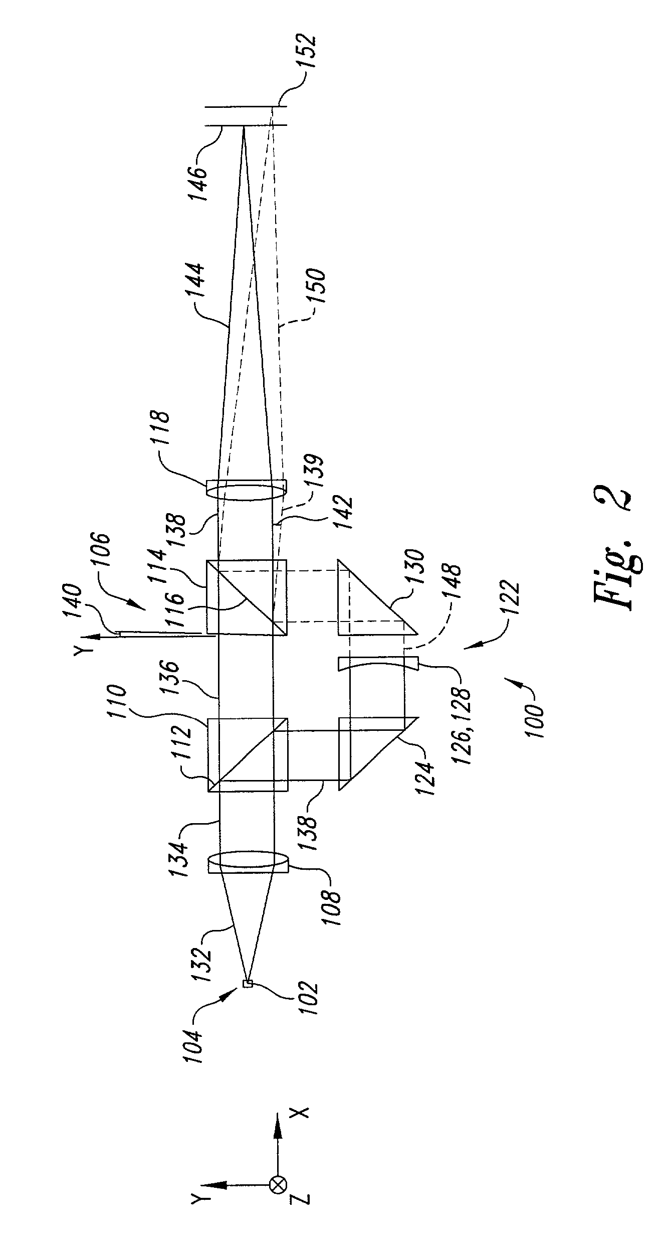
[0030]Described herein are systems and methods for achieving and maintaining focus of target objects subject to low-light, high-resolution imaging. In general, light either reflecting, scattering or emanating from a target object is collected and split into two or more light components. The optical power levels of some, but not all the light components are then modified such that when the light components are recombined with an angular separation to form an image, each of the light components have differently positioned image planes where an object point of the target object is imaged.

[0031]For each image plane pair, a detector is such that each detector receives focused images from two object planes at the target object associated with the image plane pair of the detector to increase depth of field and focusing capability. In some implementations, focus is actively maintained though computer automated positioning of components. Other implementations actively maintain focus with a f...


PUM

PropertyMeasurementUnit
diametersaaaaaaaaaa
diametersaaaaaaaaaa
focal lengthaaaaaaaaaa

Abstract

A system and method for high numeric aperture imaging systems includes a splitter, a defocusing system, and a combiner. The splitter reflects a portion of collected light and transmits another portion of the collected light. The defocusing system is configured to modify optical power of either the transmitted portion or reflected portion of the collected light. The combiner is oriented with respect to a mechanical angle. The combiner recombines portions of the transmitted portion and the reflected portion such that the transmitted portion and reflected portion are subsequently transmitted being separated by an optical separation angle based upon the mechanical angle of orientation of the combiner. Various other implementations are used to maintain focus with regards to the imaging systems involved.

Description

CROSS-REFERENCE TO RELATED APPLICATION[0001]This application claims the benefit of U.S. Provisional Patent Application No. 60 / 240,125, filed Oct. 12, 2000, incorporated herein by reference in its entirety.BACKGROUND OF THE INVENTION[0002]1. Field of the Invention[0003]The invention relates generally to imaging systems, and more particularly to systems and methods for high numeric aperture imaging involving low-light and high-resolution, such as used for microscopic imaging of biological samples or macroscopic imaging of astronomical samples.[0004]2. Description of the Related Art[0005]Low-light, high-resolution imaging involves situations where relatively little amount of light reflects, scatters or emanates from a target object to be viewed by using a high-resolution imaging system. Such low-light, high-resolution imaging can involve microscopic imaging of target objects including biological samples prepared using fluorescence in situ hybridization (FISH) or can involve macroscopic...

Claims


Application Information

Patent Timeline
07 Mar 2006
Publication
US7009651B2
IPC
H04N5/232; C07B61/00; C07K1/04; C12Q1/68; C12Q1/6816; G01N15/02; G01N15/14; G01N21/03; G01N21/05; G02B7/28; G02B21/00; G02B27/00; G02B27/14
CPC
C12Q1/6816; G01N15/147; G01N21/031; G01N21/05; G02B7/28; G02B21/00; G02B27/0012; G02B27/1086
Inventors
ORTYN, WILLIAM E.; BASIJI, DAVID A.