
Image forming apparatus

a technology of image signal and forming apparatus, which is applied in the direction of electrical apparatus casings/cabinets/drawers, instruments, semiconductor/solid-state device details, etc., can solve the problems of incorrect image formation, distorted image signal, feed failure and signal deterioration, etc., to prevent the damage of an electric cable

Inactive Publication Date: 2006-03-07
CANON KK
View PDF5 Cites 4 Cited by
  • Summary
  • Abstract
  • Description
  • Claims
  • Application Information

AI Technical Summary

Benefits of technology

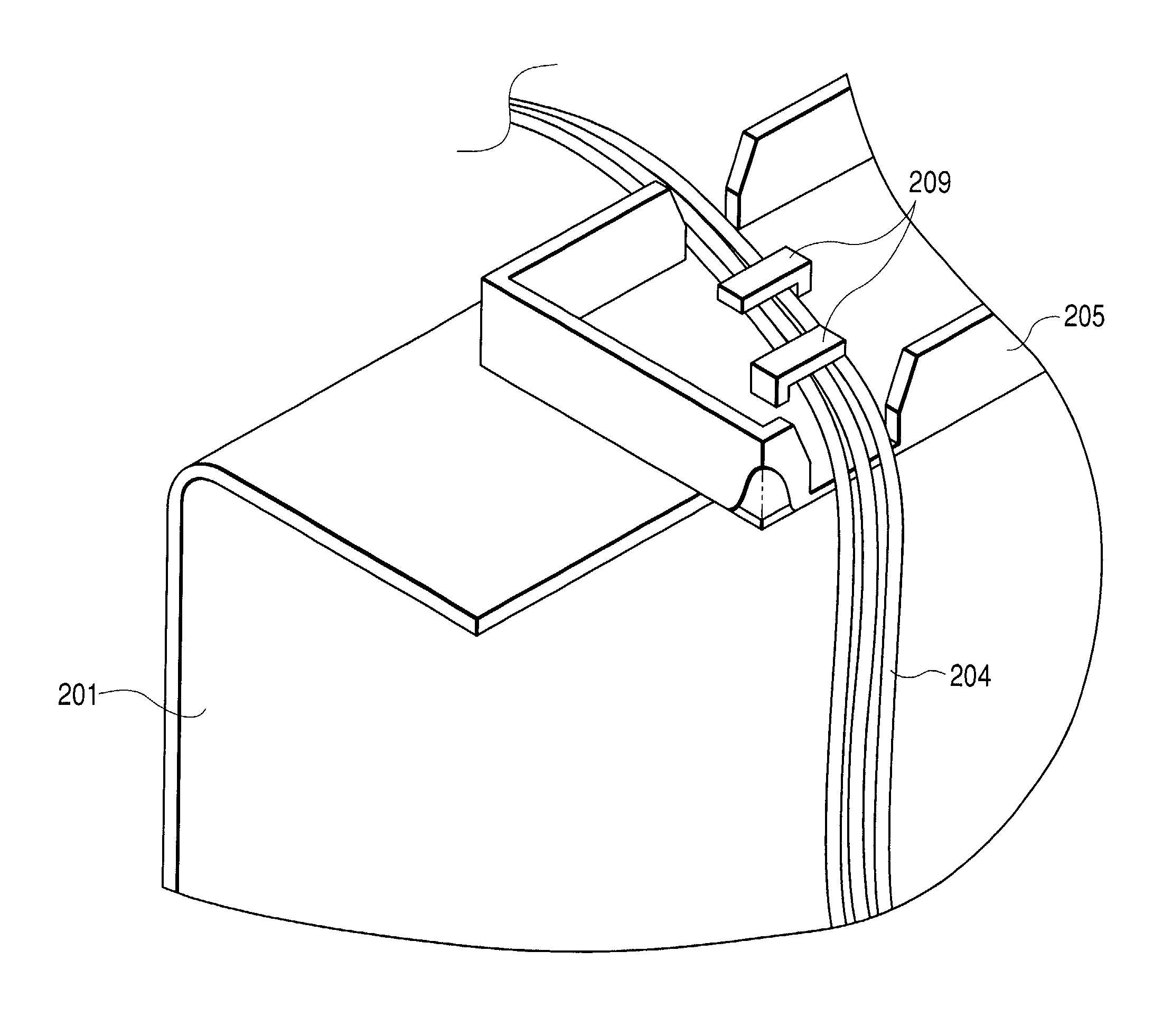
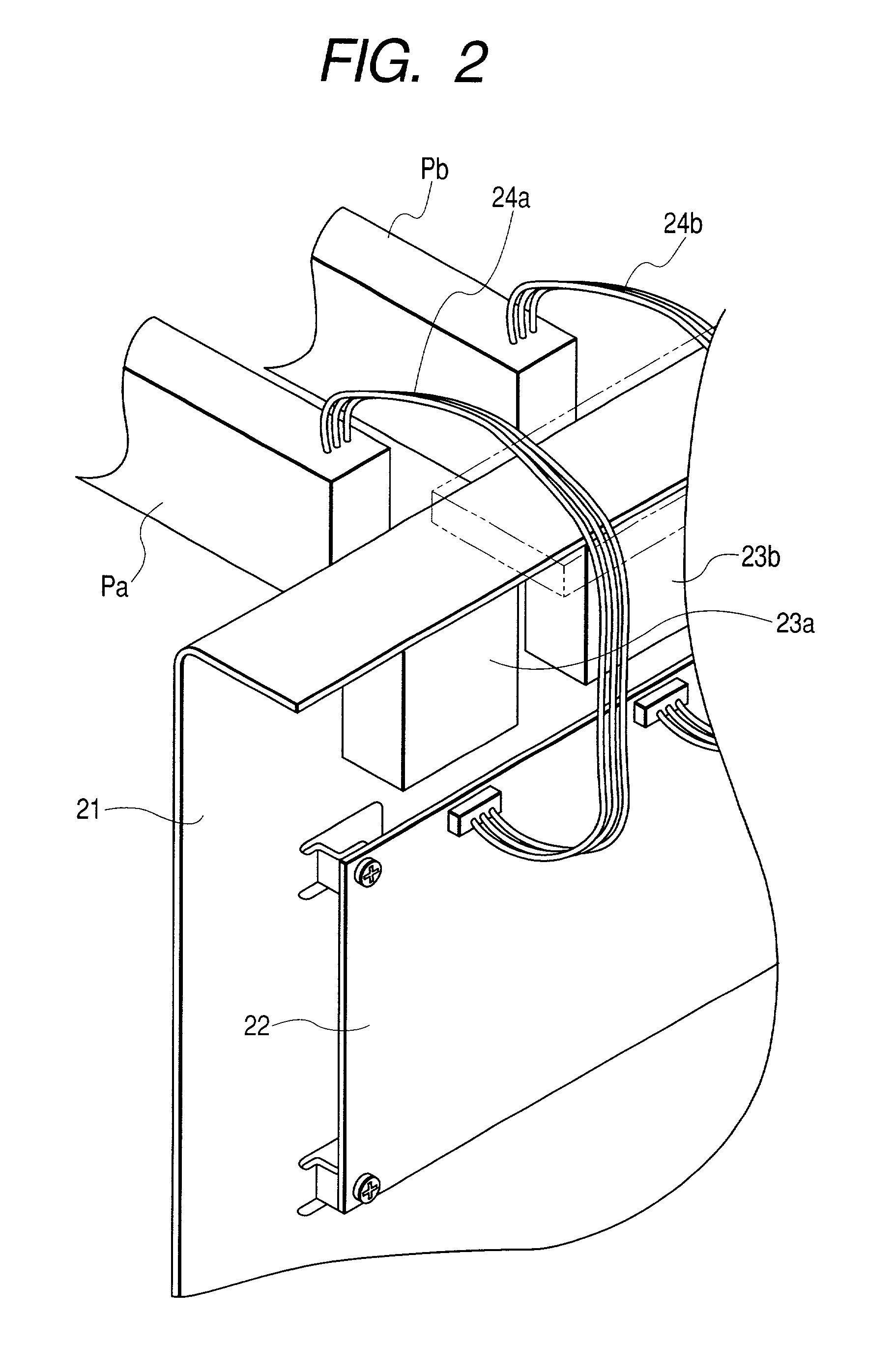
[0012]An object of the present invention is to provide an image forming apparatus which prevents the damage of an electric cable by a metal frame.

Problems solved by technology

In this case, since the edge of the sheet metal frame is sharp, the electric cable may be damaged, thereby causing feeding failure and signal deterioration.
However, since the resin block has an electric non-conductance, there arose a problem that an electric noise is generated when the cable transmits a high frequency.
Particularly, in a digital electrophotographic apparatus, the drive signal to drive a laser or a light emitting diode (LED) for exposing the photosensitive body becomes higher in frequency as a resolution and speed are increased and tends to generate the electric noise.
When this noise is superposed on an image signal, the image signal is distorted and an incorrect image is formed.

Method used


Image

  • Image forming apparatus
  • Image forming apparatus
  • Image forming apparatus

Examples


Embodiment Construction

[0023]The present invention will be described in detail below with reference to the drawings.

[0024]First, an embodiment of the present invention will be described.

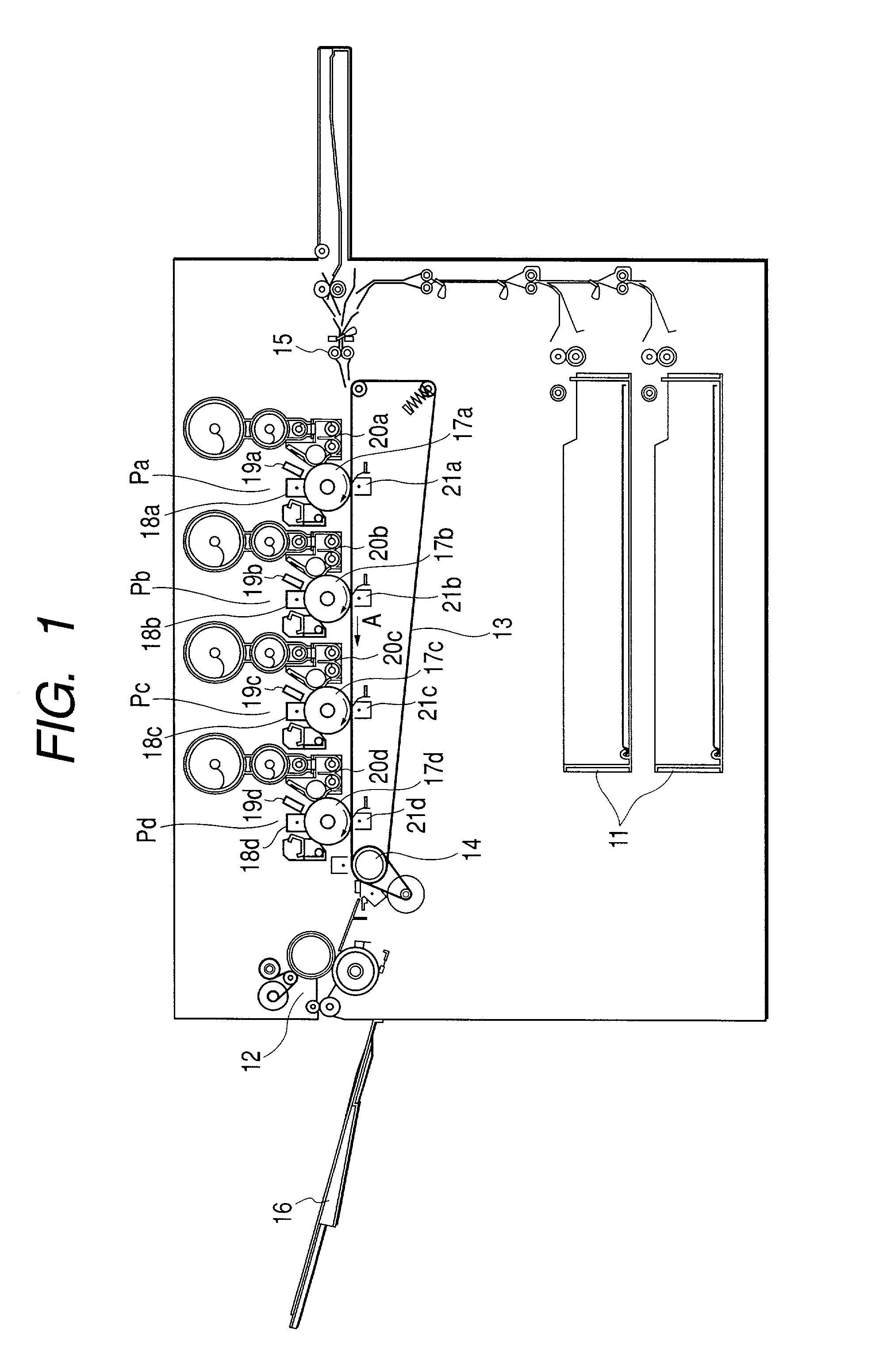
[0025]In the first place, an image forming process in the image forming apparatus adapting the electrophotographic system which is one example of the image forming apparatus according to the present embodiment will be explained with reference to FIG. 1.

[0026]In such an image forming apparatus, as shown in FIG. 1, first, second, third and fourth image forming sections Pa, Pb, Pc and Pd, which form images of respective colors of yellow, magenta, cyan and black, are installed. The image forming sections Pa, Pb, Pc and Pd comprise photosensitive drums 17a to 17d which are image bearing bodies respectively, and on which, after being evenly charged by charging means 18a to 18d, electrostatic latent images are formed by electrostatic latent image forming means 19a to 19d which use the light emitting diode as an exposure light sou...


PUM


Abstract

If an edge of a sheet metal of a image forming apparatus damages an electric cable, the image signal is distorted and no correct image is formed since the damage causes feeding failure and signal deterioration. This is remarkable in the conventional digital electrophotographic apparatus, since the drive signal to drive a laser or a light emitting diode (LED) for exposing the photosensitive body becomes higher in frequency as a resolution and speed are increased and tends to generate the electric noise. In order to prevent damage of an electric cable by a metal frame, an apparatus having a holder for holding a feed cable is provided.

Description

BACKGROUND OF THE INVENTION[0001]1. Field of the Invention[0002]The present invention relates to an image forming apparatus such as a copying machine, facsimile apparatus and the like.[0003]2. Related Background Art[0004]In general, an image forming apparatus of an electrophotographic system forms an electrostatic latent image by exposing a charged photosensitive body to an image light, and after this electrostatic latent image is developed, it is transferred on a recording medium such as a paper or the like.[0005]In such an image forming apparatus, an electric cable is used for feeding and transmitting a signal, and the cable is usually fixed to a sheet metal frame of the apparatus body.[0006]As miniaturization of the apparatus has been progressing, restriction has come to be imposed on a wiring position and fixing position of the cable and sometimes the cable may come into contact with an edge of the metal frame.[0007]In this case, since the edge of the sheet metal frame is sharp,...

Claims


Application Information

Patent Timeline
Patent Type & Authority Patents(United States)
IPC IPC(8): H01R4/58H01R4/00B41J29/00G03G15/00G03G21/00H05K5/02H05K9/00
CPCH05K5/0247
Inventor IKEDA, TARO
Owner CANON KK
Learn More