Rotary magnetic head device and method of producing a rotary magnetic head device

Inactive Publication Date: 2006-03-07
FUNAI ELECTRIC CO LTD
View PDF9 Cites 6 Cited by
  • Summary
  • Abstract
  • Description
  • Claims
  • Application Information

AI Technical Summary

Benefits of technology

[0015]It is another object of the present invention to easily adjust a force in the thrust direction by generating a force in the thrust direction by an urging member and also it is another object of the present invention to avoid an influence given by dust.
[0016]It is still another object of the present inv

Problems solved by technology

Accordingly, there is a possibility that the initial attraction characteristic of the permanent magnet is impaired.
(2) An attraction force of the permanent magnet changes being in inverse proportion to the square of a distance from the permanent magnet to an object to be attracted. Therefore, in the case of Prior Art Example 1 described before, it is necessary to highly accurately adjust a distance from the permanent magnet to the rotary transformer, which is troublesome taking time and labor.
(3) A rotary transformer is attached to the rotary side or stationary side unit, and the permanent magnet is attached to the rotary side unit. Therefore, it is indispensable to incorporate the permanent magnet inside the fluid bearing cylinder. Accordingly, the efficiency of assembling work is impaired and the productivity i

Method used


Image

  • Rotary magnetic head device and method of producing a rotary magnetic head device
  • Rotary magnetic head device and method of producing a rotary magnetic head device
  • Rotary magnetic head device and method of producing a rotary magnetic head device

Examples


first embodiment

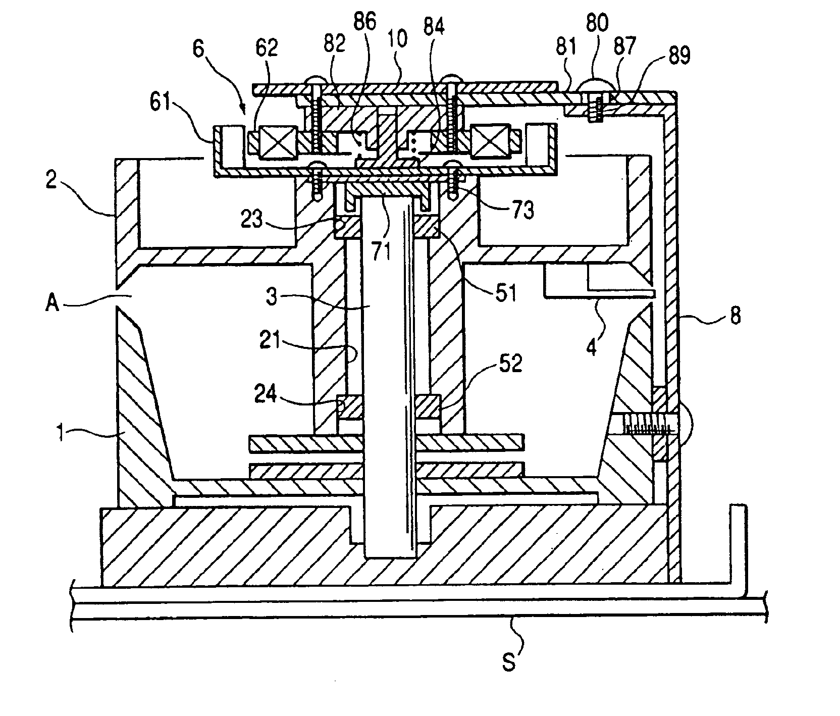
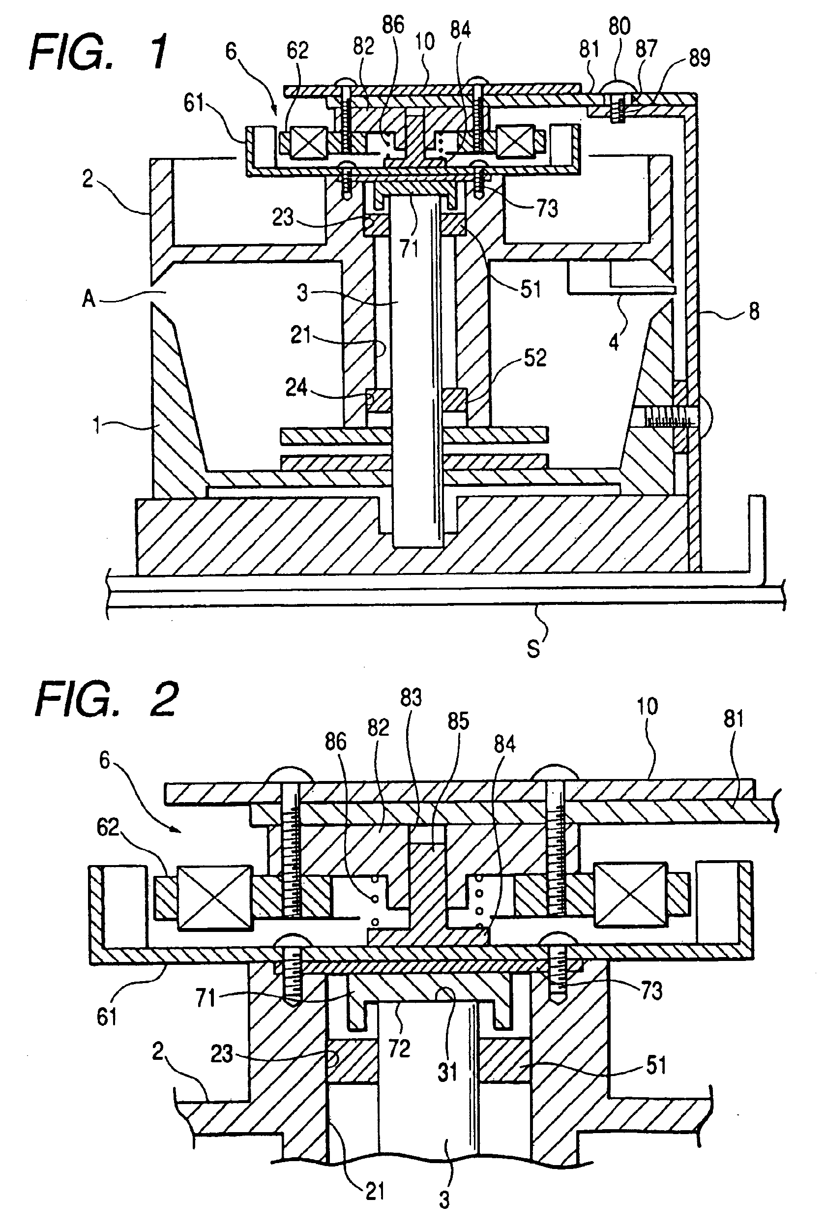
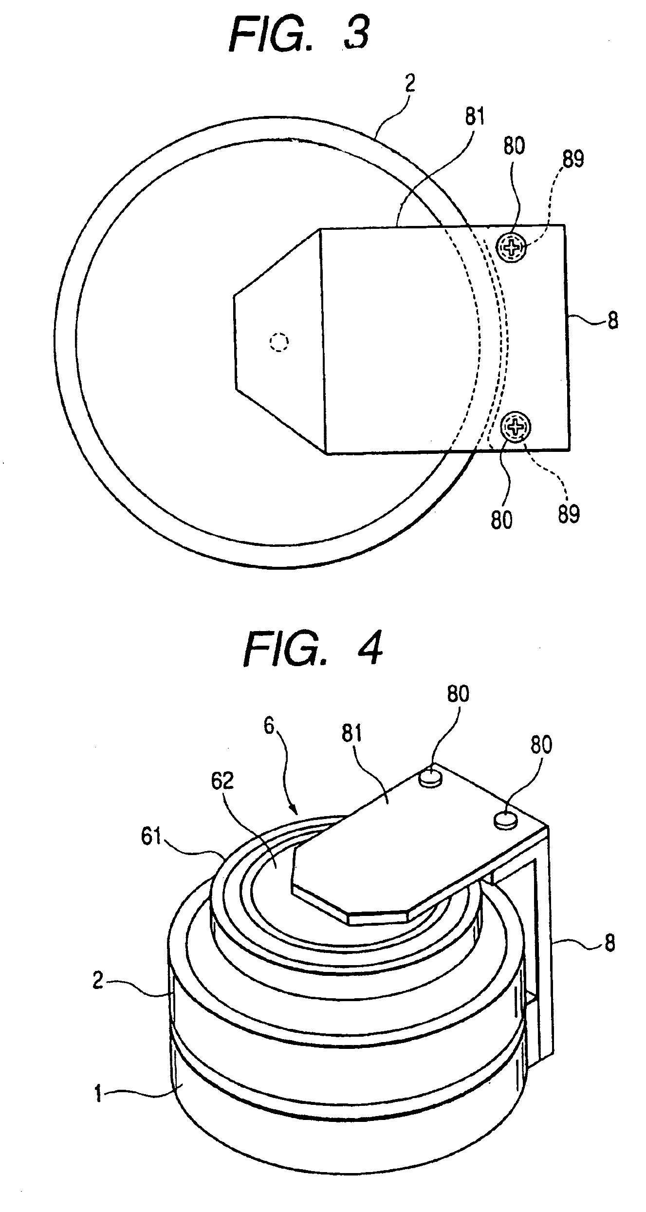
[0038]FIGS. 1 to 3 are views showing a rotary magnetic head. FIG. 1 is a longitudinal sectional side view, FIG. 2 is an enlarged longitudinal sectional side view of a primary portion of FIG. 1, and FIG. 3 is a schematic illustration showing a positional relation between an attaching member 81 and a rotary drum 2, wherein the view is taken from above. FIG. 4 is a schematic perspective view of the rotary magnetic head. FIG. 5 is an exploded perspective view showing an outline of the assembling procedure of a motor 6 and also showing an outline of a positioning jig used in an assembling process. FIG. 6 is a front view of the positioning jig.

[0039]In FIG. 1, reference numeral 1 designates a stationary drum, reference numeral 2 designates a rotary drum, and reference numeral 3 designates a support shaft used as a stationary shaft. In this structure, a lower end portion of the support shaft 3 is fixed to the stationary drum 1 being press-fitted into it.

[0040]The rotary drum 2 includes: a ...

second embodiment

[0053]FIGS. 8 to 10 are views showing a rotary magnetic head of the present invention. FIG. 8 is a longitudinal sectional side view showing an outline of the rotary magnetic head, FIG. 9 is an enlarged longitudinal sectional side view showing portion IX of FIG. 8, and FIG. 10 is a schematic illustration showing a state in which a holding piece portion of the rotor frame and an annular electrode of the thrust bearing are put on each other.

[0054]In FIG. 8, reference numeral 1 designates a stationary drum, reference numeral 2 designates a rotary drum, and reference numeral 3 designates a support shaft used as a stationary shaft. In this structure, a lower end portion of the support shaft 3 is fixed to the stationary drum being press-fitted into it.

[0055]As shown in FIG. 8, the rotary drum 2 includes: a magnetic head 4; a central through-hole 21; and bearing attaching portions 23, 24, the diameters of which are large, which are recess portions formed concentrically with the through-hole...

third embodiment

[0067]FIG. 15 is a view showing a rotary magnetic head of the present invention.

[0068]In FIG. 15, reference numeral 1 designates a stationary drum, reference numeral 2 designates a rotary drum, and reference numeral 3 designates a support shaft used as a rotary shaft. In this structure, an upper end portion of the support shaft 3 is fixed to the rotary drum 2 being press-fitted into it.

[0069]As shown in FIG. 15, the stationary drum 1 includes a central through-hole 21b. The radial bearings 51, 52 are respectively press-fitted into the two portions of the through-hole 21b, wherein one is an upper portion and the other is a lower portion of the through-hole 21b. These radial bearings 51, 52 are oil impregnated powder sintered bearings in which lubricant is impregnated in a cylindrical sintered metal body.

[0070]In the rotary drum 2, there is provided an annular flat attaching portion 27 outside the rib 26. A rotor 61 of the motor 6, which will be described later, is attached to this at...


PUM


Abstract

A rotary magnetic head device includes a stationary drum; a rotary drum having a rotary magnetic head; a rotor of a motor fixed to the rotary drum; a support shaft for pivotally supporting the rotary drum, the support shaft having a receiving face; a radial bearing for receiving a radial load, interposed between the rotary drum and the support shaft; a thrust bearing for receiving a thrust load, being slidably put on the receiving face; an urging member for urging the thrust bearing against the receiving face by pushing the rotary drum downward; and a reverse L-shaped support fixed to the stationary drum. The urging member is supported by the reverse L-shaped support and arranged on the rotary drum.

Description

BACKGROUND OF THE INVENTION[0001]1. Field of the Invention[0002]The present invention relates to a rotary magnetic head device used for a video tape recorder, which will be referred to as “VTR” in this specification, hereinafter. More particularly, the present invention relates to a rotary magnetic head device in which a rotary drum having a magnetic head is supported by a support shaft, which is a stationary shaft, via a bearing.[0003]2. Description of the Related Art[0004]According to Japanese Unexamined Patent Publication No. 58-180828 (Prior Art Example 1), there is a description about a fluid bearing cylinder device having a rotary side unit and stationary side unit. This Prior Art Example 1 describes the fluid bearing cylinder device as follows. A rotary transformer is attached to the stationary side unit, and a permanent magnet is attached to the rotary side unit. When this permanent magnet is opposed to the rotary transformer, a predetermined attraction force is generated in...

Claims


Application Information

Patent Timeline
IPC IPC(8): G11B21/04G11B5/53
CPCG11B5/53
Inventor SAWAI, KUNIOTAKAHASHI, KAZUHIRO
Owner FUNAI ELECTRIC CO LTD
Why Eureka
Try Eureka