Thermal regulation of a coated work-piece during the reconfiguration of the coated work-piece

a technology of coating workpiece and reconfiguration, which is applied in the field of coating workpiece protection, can solve the problems of reducing the effectiveness of finished products, damage to the coating of workpieces, and exposed surfaces of finished products that are more susceptible to corrosion than if their coating is not applied,

Inactive Publication Date: 2006-03-14
BOSTON SCI SCIMED INC
View PDF29 Cites 37 Cited by
  • Summary
  • Abstract
  • Description
  • Claims
  • Application Information

AI Technical Summary

Benefits of technology

[0008]Apparatus for configuring an externally coated workpiece are provided. In one example, the apparatus includes a tubular reconfiguration chamber having a plurality of slidably mounted outer walls, the outer walls slidably mounted along individual radial lines emanating from and orthogonal to the central longitudinal axis of the tubular reconfiguration chamber; and a means for adjusting and maintaining the temperature of the external coating of a work-piece located within the tubular reconfiguration chamber.
[0009]In another example the apparatus includes a reconfiguration chamber; a n...

Problems solved by technology

In either of these, as well as in others, damage to the coating of a work-piece, resulting from the handling or reconfiguration of the work-piece, is an unwanted result.
When the coating of a work-piece becomes scratched or otherwise damaged during the work-piece's manufacture, the scratches can promote the deterioration of the work-piece by exposing the work-piece's surface to its surroundings.
Should the work-piece, upon its completion, be employed in a corrosive environment, the exposed surface of the finished product would be more vulnerable to corrosion than if its coating were completely intact.
Moreover, the scratches and inconsistencies in the coating of the work-piece may also reduce the effect...

Method used


Image

  • Thermal regulation of a coated work-piece during the reconfiguration of the coated work-piece
  • Thermal regulation of a coated work-piece during the reconfiguration of the coated work-piece
  • Thermal regulation of a coated work-piece during the reconfiguration of the coated work-piece

Examples


Embodiment Construction

[0021]In one embodiment of the present invention the hardness or resilience of the coating of a work-piece is temporarily increased by adjusting its preexisting temperature to be closer to its glass transition temperature. Then, while the coating is in this temporarily hardened or more resilient state, the force required to reconfigure the work-piece is applied against the coating. By temporarily increasing the hardness of the coating through its change in temperature, the coating is better able to withstand the forces and pressures exerted upon it during the reconfiguration of the work-piece. Thus, the coating is more likely to remain intact both during the remainder of the manufacturing of the work-piece and after the work-piece has been completely manufactured and is employed for its intended purpose.

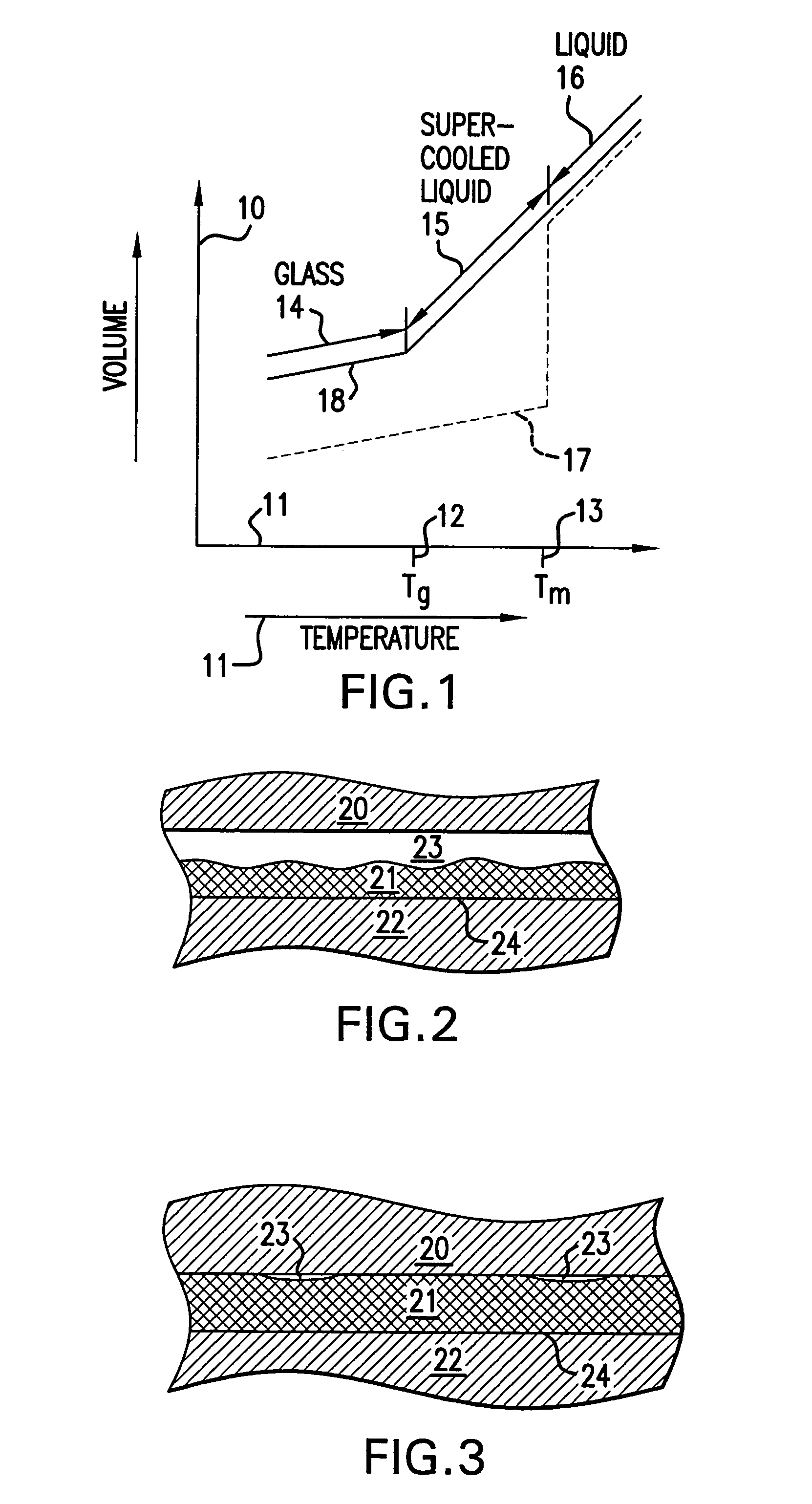
[0022]FIG. 1 is a graph of volume versus temperature for a polymer that may be used as a coating in accord with one embodiment of the present invention. The temperature of the polyme...


PUM

PropertyMeasurementUnit
Surface temperatureaaaaaaaaaa
Temperatureaaaaaaaaaa

Abstract

Apparatus for configuring an externally coated workpiece are provided. In one example, the apparatus includes a tubular reconfiguration chamber having a plurality of slidably mounted outer walls, the outer walls slidably mounted along individual radial lines emanating from and orthogonal to the central longitudinal axis of the tubular reconfiguration chamber; and a device for adjusting and maintaining the temperature of the external coating of a work-piece located within the tubular reconfiguration chamber. In another example the apparatus includes a reconfiguration chamber; a nozzle in fluid communication with the reconfiguration chamber, a regulator in fluid communication with the nozzle, the regulator adapted to regulate the flow of a thermal transfer fluid exiting the nozzle, and a controller in communication with the regulator, the controller adapted to send control signals to the regulator to maintain the surface temperature of the external coating of the reconfigurable work-piece within a predetermined temperature range, the predetermined temperature range associated with a predetermined minimum hardness of the external coating of the reconfigurable work-piece.

Description

CROSS-REFERENCE TO RELATED APPLICATIONS[0001]This application is a Continuation of application Ser. No. 09 / 819,638, filed Mar. 29, 2001 now U.S. Pat. No. 6,739,033, which is included herein in its entirety by reference.TECHNICAL BACKGROUND[0002]The present invention regards protecting a coated work-piece during its manufacture or reconfiguration. More specifically the present invention regards reducing the probability of damaging the coating of a work-piece during the work-piece's manufacture by managing or regulating the temperature of the coating.BACKGROUND OF THE INVENTION[0003]Articles of manufacture are regularly coated for numerous and varying reasons. For example, they may be coated to protect them from the intrusive handling they may be subjected to during their manufacture or to protect them from the environmental effects they may endure after they are manufactured. In either of these, as well as in others, damage to the coating of a work-piece, resulting from the handling ...

Claims


Application Information

Patent Timeline
IPC IPC(8): B23P11/00A61F2/00B29B13/02B29C67/00
CPCB29B13/02B29C67/0014A61F2240/001B29L2031/7532Y10T29/49913Y10T29/5383Y10T29/53009Y10T29/49771Y10T29/53013Y10T29/49927Y10T29/53996Y10T29/49865
Inventor HIJLKEMA, LUUKAUSTIN, MICHAELWEBER, JAN
Owner BOSTON SCI SCIMED INC
Why Eureka
Try Eureka