Corrosion resistant valve guide

a valve guide and corrosion resistance technology, applied in the direction of valve arrangements, machines/engines, mechanical equipment, etc., can solve the problems of premature failure of the valve guide, corrosion of both the valve and the valve guide, and the valve guide is subject to extremely high thermal and mechanical stress, so as to prevent acidic corrosion and prevent condensation of h2so4

Active Publication Date: 2010-03-04
ELECTRO-MOTIVE DIESEL
View PDF3 Cites 0 Cited by
  • Summary
  • Abstract
  • Description
  • Claims
  • Application Information

AI Technical Summary

Benefits of technology

[0008]The present invention generally relates to a new valve guide for use in an exhaust valve system. Specifically, the invention is related to a valve guide that prevents acidic corrosion between the valve and the valve guide. The valve guide includes a number of contact portions, which engage the channel that is formed in the cylinder head near the exhaust port. The valve guide also includes a recess portion, situated in relation to a water jacket and between the contact portions. The recess portion and contact portions are sized and shaped to maintain the surface temperature of the valve guide to prevent condensation of H2SO4 between the valve stem and the valve guide.
[0009]Additionally, the present invention is directed towards a method for maintaining the surface temperature of the valve guide to prevent acidic corrosion that includes the step of extending the valve guide into an exhaust port to increase the surface temperature of the valve guide. Further provided is a method for sizing and shaping the recess portion relative to the water jacket to control the surface engagement between the valve guide and the cylinder head so as to maintain surface temperature to prevent condensation of acidic gases. This method also includes the step of sizing a clearance in the valve guide near the exhaust port to allow exhaust gases to surround a portion of the valve guide to further control surface temperature of the valve guide.

Problems solved by technology

In general, valve guides and valves are subject to extremely high thermal and mechanical stress.
Due to the duty cycle imposed on engines and the possible use of different grades of diesel, the valve guide is subjected to increased levels of acid which condenses thereon, resulting in corrosion and premature failure of the valve guide.
As a result, acid forms between the valve guide and the valve, resulting in corrosion of both the valve and the valve guide.
Diesel engines operating on high sulfur fuels periodically require grinding of the exhaust valves and seats employed therein due to corrosion effects and exposure to high heat levels and the acid formed thereon.
Such corrosion tends to induce a channeling or guttering of the valve faces which accelerates such corrosion and gives rise to gas leakage past the valves and potential breakage of the valve heads.
Additionally, valve guides in traditional valve train systems are subject to corrosion due to the acid formed thereon.
As a result, such valve guides were readily worn and corroded during operation of the engine.
However, due to the increased cost of Nickel, a dominant constituent in the Ni-Resist alloy, the part cost has increased significantly.

Method used


Image

  • Corrosion resistant valve guide
  • Corrosion resistant valve guide
  • Corrosion resistant valve guide

Examples


example 2

[0031]FIGS. 4A and 4B illustrate another embodiment of the present invention where the valve guide 400 does not extend into the exhaust port 408 and has more contact than in the embodiment illustrated in FIGS. 3A and 3B. The valve guide 400 is situated in a channel 402 formed between the valve 404 and the cylinder head 406. The valve guide 400 guides the valve stem 414 through the channel 402, which further joins the upper portion of the cylinder head 406 to an exhaust port 408.

[0032]In order to maintain the surface temperature of the valve guide 400 across the length thereof, a recess portion 412 is sized and shaped relative to the water jacket 410 to control the surface engagement between the valve guide 400 and the cylinder head 406. The radial thickness of the cylinder head wall 416 between the water jacket 410 and the channel 402, where the valve guide 400 is situated, is about 0.313 inches. The water jacket 410 is generally maintained at a temperature between about 175° F. and...

example 3

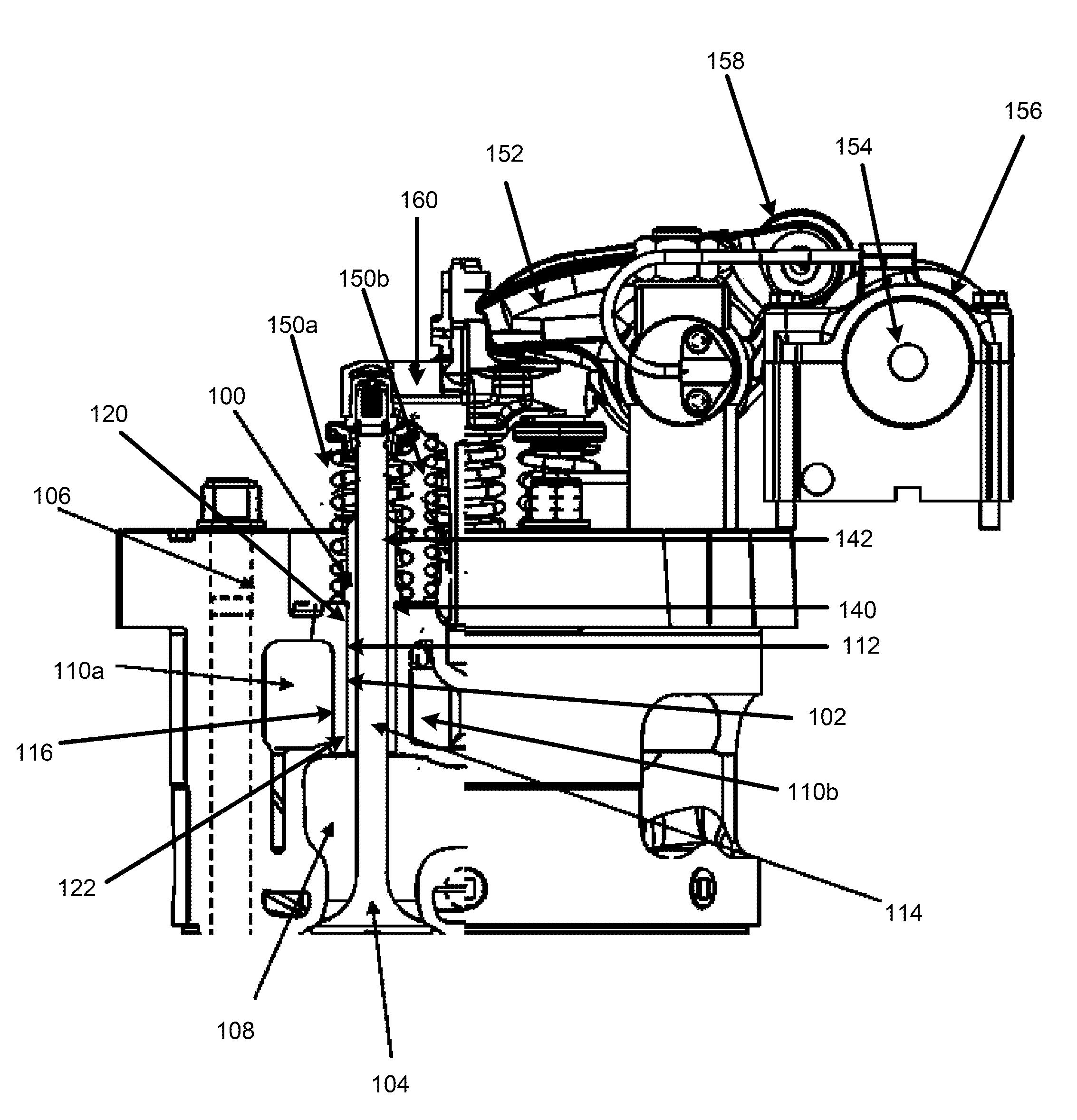
[0036]In yet another embodiment of the present invention, as shown in FIGS. 5A and 5B, a valve guide 500 has the most contact with the cylinder head wall 516 compared to the other embodiments of the present invention. The valve guide 500 is situated in a channel 502 formed between a valve 504 and a cylinder head wall 516. The cylinder head wall 516 generally has a radial thickness of about 0.313 inches between the water jacket 510 and the channel 502. The valve guide 500 guides the valve stem 514 through the channel 502, which further joins the upper portion of the cylinder head 506 to an exhaust port 508. The cylinder head 506 includes a water jacket 510, which is disposed near the channel 502. The water jacket 510 is generally maintained at a temperature between about 175° F. and about 195° F. The surface temperature of the valve guide 500 is generally maintained above the critical temperature of 229° F. to avoid condensation, and thereby acidic corrosion. Although temperatures ma...

example 4

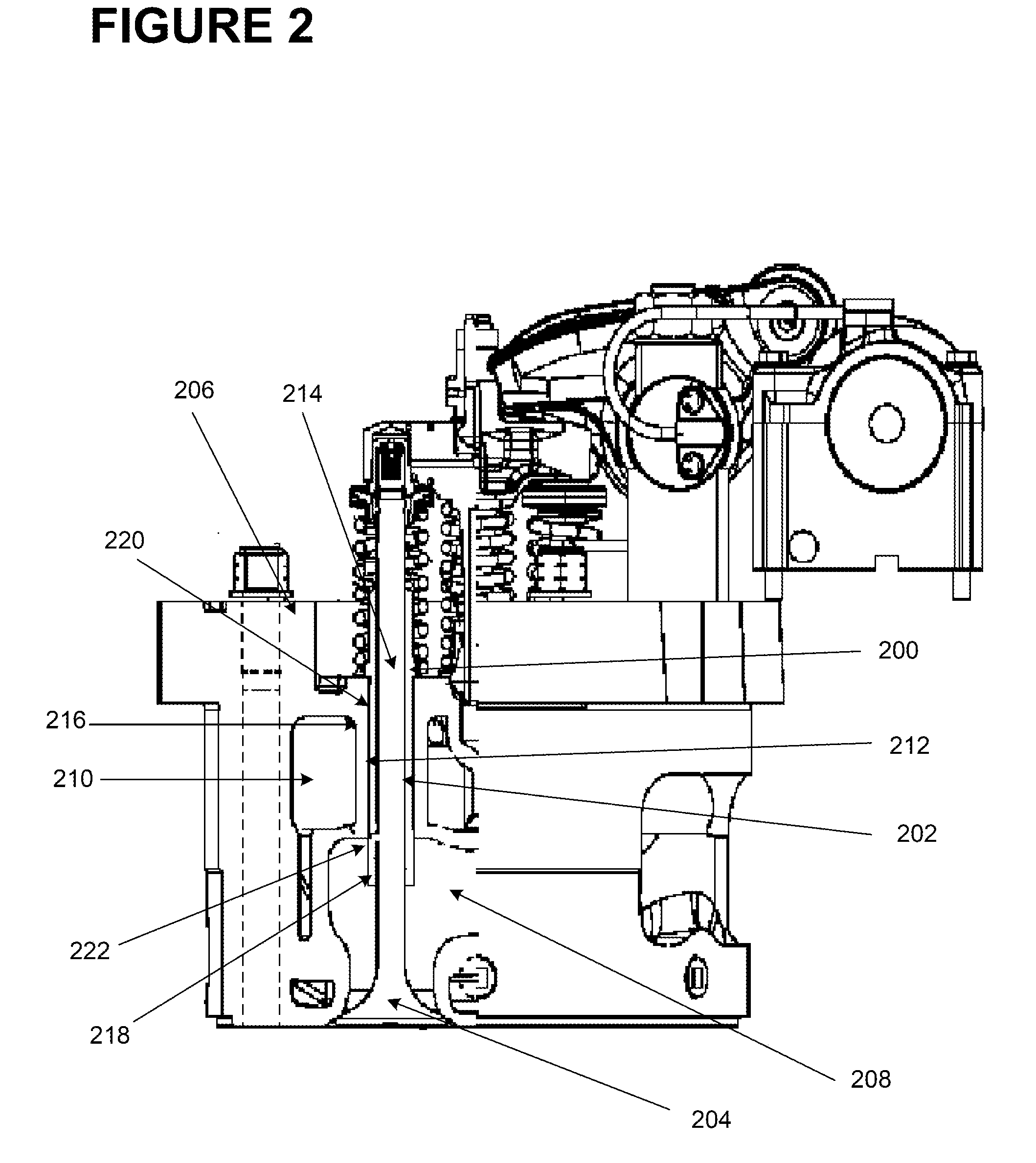
[0040]FIGS. 6A and 6B illustrate yet another embodiment of the present invention where an extended valve guide 600 has two contact portions 620, 622 and a recess portion 612. The valve guide 600 is situated in a channel 602 formed between the valve 604 and the cylinder head 606. The valve guide 600 guides the valve stem 614 through the channel 602, which further joins the upper portion of the cylinder head 606 to an exhaust port 608. The cylinder head 606 includes a water jacket 610, which is disposed near the channel 602.

[0041]In this embodiment, the valve guide 600 includes an extended portion 618 which extends into the exhaust port 608, for heating thereof. The temperature in the exhaust port 608 may be between about 600° F., when the engine is at an idle position, and about 1000° F., when the engine is in full-throttle. The hottest portion of the valve guide 600—the extended portion 618—is heated by the exhaust port 608 and then heats the entire valve guide 600, thereby maintain...


PUM


Abstract

The present invention generally relates to a new valve guide for use in an exhaust valve system. Specifically, the invention is related to a valve guide that prevents acidic corrosion between the valve and the valve guide. The valve guide includes a number of contact portions, which engage the channel that is formed in the cylinder head near the exhaust port. The valve guide also includes a recess portion, situated in relation to a water jacket and between the contact portions. The recess portion and contact portions are sized and shaped to maintain the surface temperature of the valve guide to prevent condensation of acidic gases between the valve stem and the valve guide.

Description

BACKGROUND OF THE INVENTION[0001]The present invention generally relates to a new valve guide for use in an exhaust valve system. Specifically, the invention is directed to a valve guide that maintains the temperature of its surface in order to prevent condensation of acidic gases, and thereby corrosion, of the valve and the valve guide. Additionally, the present invention is directed towards a method of maintaining the surface temperature of the valve guide in order to prevent corrosion.[0002]It is known in the art relating to internal combustion engines, such as diesel engines (e.g., locomotive diesel engines), to actuate two adjacent valves of an engine cylinder by a rotating cam. For example, in FIG. 1, the cam 154 includes a select shape which determines the timing of valve 104 actuation. In order to open the valves 104, the cam 154 rotates until a cam lobe 156 engages a roller 158 located on a rocker arm 152. Once the cam lobe 156 engages the rocker arm 152, the rocker arm 152...

Claims


Application Information

Patent Timeline
Patent Type & Authority Applications(United States)
IPC IPC(8): F01L3/08
CPCF01L3/12F01L3/08
Inventor REXAVIER, RAJIMACVICAR, ROBERT T.CRYER, III, EDWARD J.
Owner ELECTRO-MOTIVE DIESEL
Why Eureka
Try Eureka