Method for producing molded solid fuel

a technology of solid fuel and manufacturing method, which is applied in the direction of solid fuels, waste based fuels, petroleum industry, etc., can solve the problems of high temperature difference between the surficial portion and the inside, friction between the roll surface of the double-roll molding machine and the powdery upgraded coal, and the low molding cost. , to achieve the effect of reducing the occurrence of strain, high strength and high strength

Active Publication Date: 2017-08-22
KOBE STEEL LTD
View PDF11 Cites 0 Cited by
  • Summary
  • Abstract
  • Description
  • Claims
  • Application Information

AI Technical Summary

Benefits of technology

[0020]In the method of manufacturing the molded solid fuel according to the invention, the coolant is sprayed onto the surface of the molding machine to cool the surface so that the surface temperature of the molding machine is maintained to 100° C. or lower. Consequently, the molded solid fuel has a small temperature difference between the surficial portion and the inside thereof compared with the case where no coolant is sprayed, leading to suppression of occurrence of strain. As a result, a molded solid fuel having high strength can be provided.
[0021]In the method of manufacturing the molded solid fuel according to the invention, as described above, the surface temperature of the molding machine is maintained to 100° C. or lower, and the molding step is performed in the semi-sealed molding chamber while the inside of the molding chamber is humidified to maintain the humidity in the molding chamber to 85% or more. Consequently, in the molded solid fuel, occurrence of strain is suppressed as described above, and evaporation of water is suppressed due to the humidification. The molded solid fuel therefore has a small difference in moisture percentage between the surficial portion and the inside thereof, and is thus homogenized. As a result, a molded solid fuel having high strength can be provided.
[0022]In the method of manufacturing the molded solid fuel according to the invention, water is sprayed as the coolant onto the surface of the molding machine. Water has high specific heat and high evaporative latent heat and thus has a high cooling effect, and furthermore is inexpensive; hence, water is preferred as the coolant. The powdery upgraded coal is produced through dehydrating low-grade coal in oil as described above, and has a hydrophobic (lipophilic) surface. Hence, for example, an organic coolant such as lubricating oil is compatible with the powdery upgraded coal, which impairs nipping of the powdery upgraded coal between the rolls of the molding machine. Consequently, a molded material having high strength may not be provided. Using water as the coolant decreases a nip angle (biting angle into the molding machine) and improves nipping of the coal between the rollers. Consequently, a molded material having further high strength can be provided.

Problems solved by technology

In the manufacturing method described in PTL 1, however, the binder must be mixed in the powdery material coal for pressure molding, and thus lower molding cost has been an issue.
In the manufacturing method described in PTL 2, although a molded material having high strength is produced due to water addition in the humidification step, when a powdery coal having a low carbonization level and a low bulk density is molded, the strength improving effect is not sufficiently exhibited, leaving room for further improvement.
In addition, friction occurs between each roll surface of the double-roll molding machine and the powdery upgraded coal during the pressure molding by the double-roll molding machine.
As a result, a surficial portion of the molded solid fuel has even higher temperature, leading to a large temperature difference between the surficial portion and the inside thereof.
Hence, the molded solid fuel has internal strain due to the temperature difference, and is reduced in strength.
As a result, a large difference in moisture percentage occurs between the surficial portion and the inside of the molded solid fuel.
Hence, the molded solid fuel is reduced in strength due to the difference in moisture percentage.

Method used


Image

  • Method for producing molded solid fuel
  • Method for producing molded solid fuel
  • Method for producing molded solid fuel

Examples


example 1

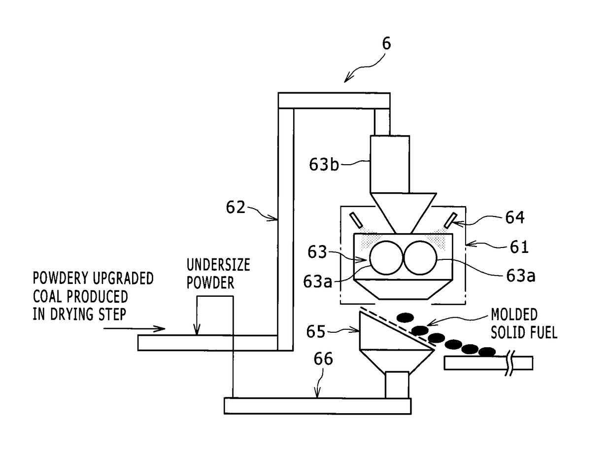
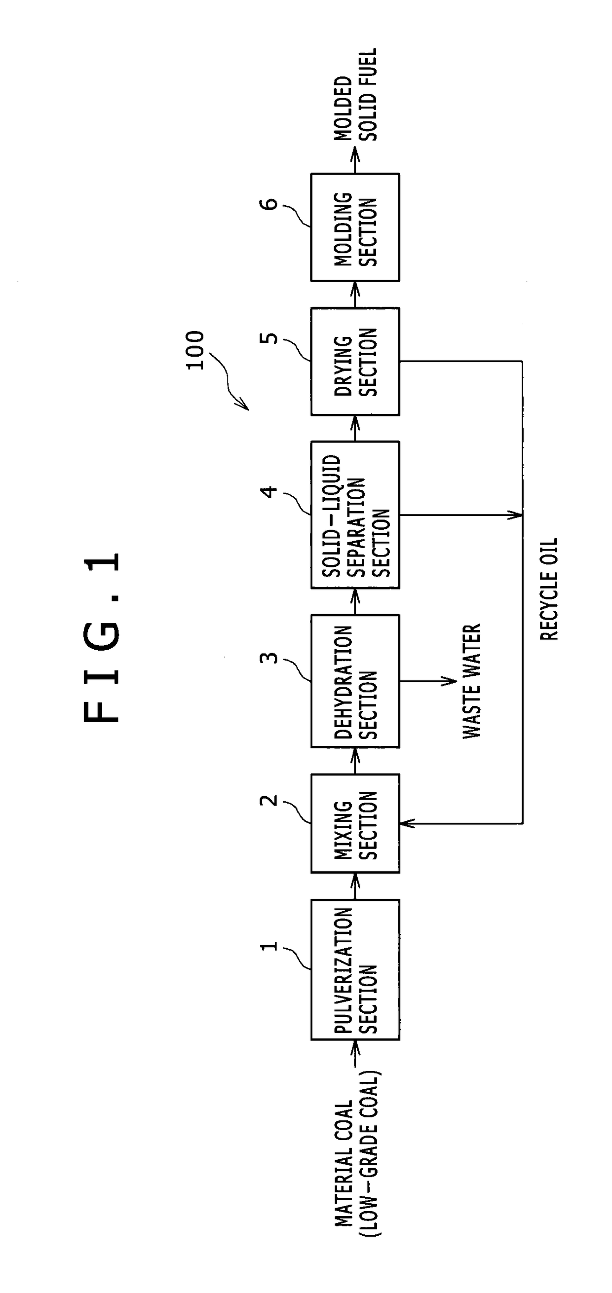
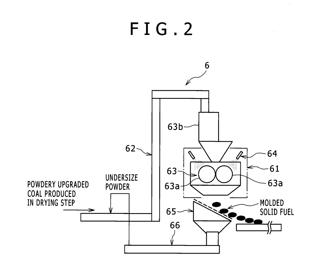
[0043]Mulia coal, which is Indonesian brown coal, was used as low-grade coal as a material. The Mulia coal was pulverized by a hummer crusher in the pulverization section 1 and was formed into particles having a maximum particle size of 3 mm or less and an average particle size of about 0.5 mm. Such pulverized low-grade coal was subjected to separation treatment of dust coal, so that dust coal particles having an average particle diameter of about 0.1 mm or less were removed. The mixing section 2 then mixed the low-grade coal, from which the dust coal had been removed, and kerosene as the solvent oil, and thus produced a slurry. In such mixing, a weight ratio of the pulverized low-grade coal to the solvent oil was adjusted to 1.7 with reference to dried or moisture-free coal. The slurry produced in this way was sequentially subjected to the steps performed by the dehydration section 3, the solid-liquid separation section 4, and the drying section 5 to produce powdery upgraded coal.

[...


PUM

PropertyMeasurementUnit
roll surface temperatureaaaaaaaaaa
humidityaaaaaaaaaa
roll surface temperatureaaaaaaaaaa

Abstract

A method of manufacturing a molded solid fuel including: a pulverization for pulverizing low-grade coal; a mixing for obtaining a slurry by mixing the pulverized low-grade coal and a solvent oil; a dehydration for obtaining a dehydrated slurry by heating and dehydrating the slurry; a solid-liquid separation for obtaining a cake by separating the solvent oil from the dehydrated slurry; a drying for obtaining powdery modified coal by heating the cake and further separating the solvent oil from the cake; and a molding for pressurizing and molding the powdery modified coal by using a molding machine, without the addition / mixture of a binder. In the molding, a coolant is sprayed onto the surface of the molding machine, and the surface temperature of the molding machine is kept equal to or below 100° C.

Description

TECHNICAL FIELD[0001]The present invention relates to a method of manufacturing a molded solid fuel from low-grade coal such as brown coal and subbituminous coal.BACKGROUND ART[0002]A manufacturing method described in PTL 1 (Japanese Unexamined Patent Application Publication No. Sho57(1982)-151696) has been known as a method of manufacturing molded coal through pressure-molding of powdery material coal. In this manufacturing method, dried powdery molding material coal and a binder such as coal-tar pitch are blended, and such a blend is pressure-molded to produce molded coal. Specifically, in this manufacturing method, a water coating is formed on a mold surface of a molding machine by water spray or steam blowing, and then the blend is pressure-molded.[0003]This manufacturing method described in PTL 1 is intended to prevent insufficient removal of molded coal from the mold. In the manufacturing method, therefore, a water coating is formed on the mold surface, thereby wettability of ...

Claims


Application Information

Patent Timeline
Patent Type & Authority Patents(United States)
IPC IPC(8): C10L5/02C10L5/08C10L5/04C10L9/00C10L5/36B29C67/00C10L5/06C10L9/10
CPCC10L5/08C10L5/04C10L5/361C10L9/00C10L9/10C10L2200/043C10L2290/06C10L2290/08C10L2290/18C10L2290/24C10L2290/28C10L2290/30C10L2290/32C10L2290/546C10L2290/547Y02E50/30
Inventor TAKAHASHI, YOICHISHIGEHISA, TAKUOADACHI, TSUYOSHI
Owner KOBE STEEL LTD
Why Eureka
Try Eureka