Surface particle detector

a particle detector and surface technology, applied in the field of particle counting, can solve the problems of not providing quantitative data, allowing a cursory inspection of the surface conditions, and both suffer from the same limitations

Inactive Publication Date: 2006-03-14
PENTAGON TECH GROUP
View PDF42 Cites 26 Cited by
  • Summary
  • Abstract
  • Description
  • Claims
  • Application Information

AI Technical Summary

Benefits of technology

[0010]In yet one more aspect of the present invention, the device includes a scanner having at least one opening for receiving particles from a sample surface, a particle counter for analyzing particles passed therethrough, and a conduit having a first end connected to the scanner and a second end connected to the particle counter. The conduit includes first and second tubes. The particle counter includes a pump for producing an airstream flowing from the scanner opening, through the first tube, through the particle counter, and back to the scanner via the second tube, for carrying the particles to the particle counter. The particle counter also includes a particle detector for counting the particles in the airstream coming from the scanner, a filter cartridge port through which the airstream flows after passing through the particle detector, and a filter cartridge removably connected to the filter cartridge port for capturing the particles in the airstream after being counted by the particle detector.

Problems solved by technology

While the white light technique is slightly more sensitive than the ultraviolet technique, they both suffer from the same limitations.
These visual inspection techniques only allow a cursory inspection of the surface conditions.
They do not provide quantitative data.
Also, the visual inspection techniques, at best, only detect particles that are larger than twenty microns.
The primary disadvantage of this technique is that it is very time consuming, and that it is highly sensitive to variability between operators.

Method used


Image

  • Surface particle detector
  • Surface particle detector
  • Surface particle detector

Examples


Embodiment Construction

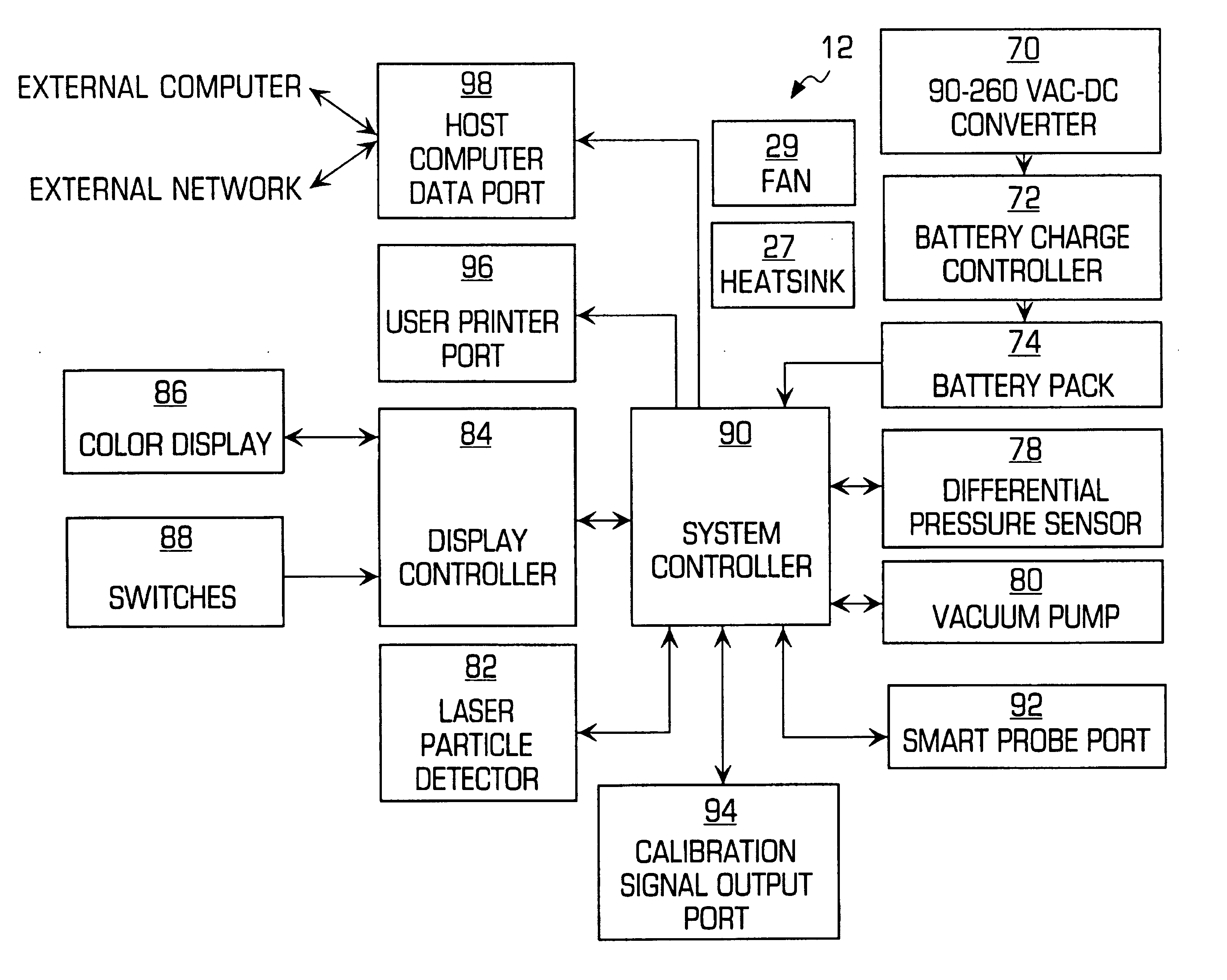
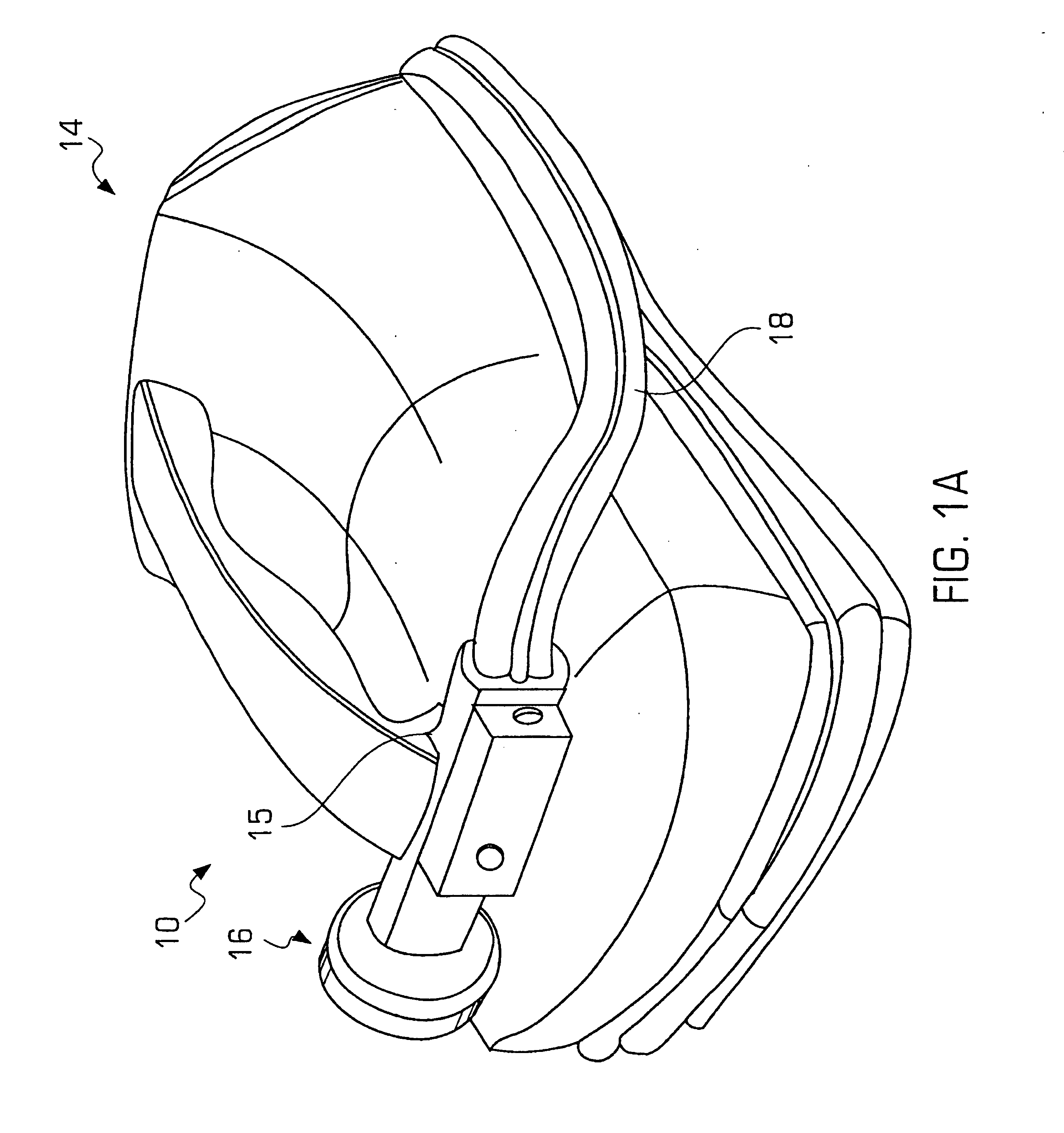
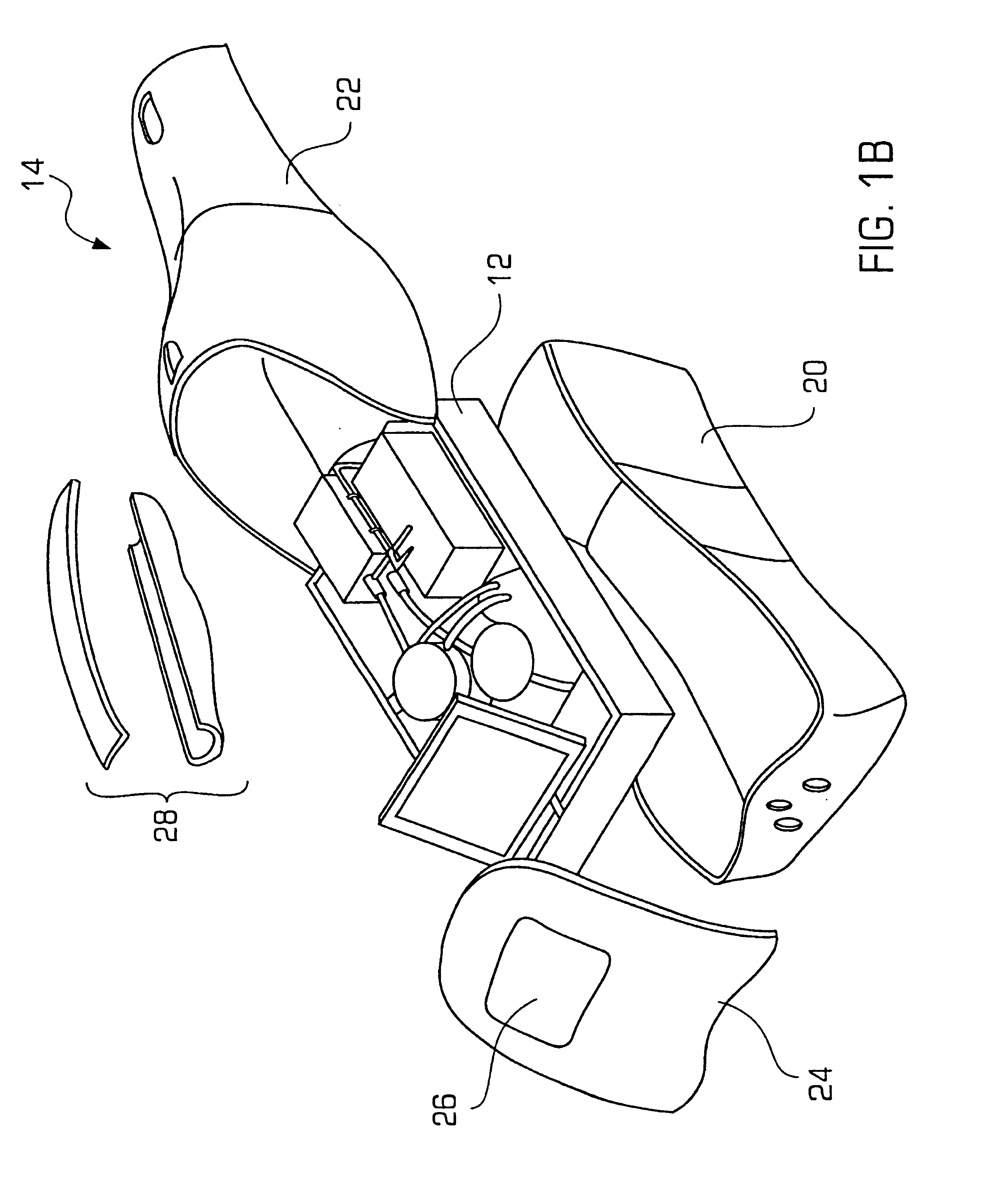
[0021]The present invention is an improved surface particle detector, relative to the particle detector disclosed in U.S. Pat. No. 5,253,538, which is expressly incorporated herein by reference. The present invention advantageously employs in operable combination three primary elements to provide the flexibility of conveniently sampling particles on a wide variety of surfaces, while also providing relative quantitative data with a high degree of precision and repeatability. In broad terms, the invention involves the combination of a state-of-the-art particle counter connected to one of a plurality of specially designed and sized sampling scanners via a flexible conduit. In a preferred embodiment the conduit has two air tubes and electrical wires for supplying and returning air to and from the sample surface and for powering the scanner. The light weight moveable scanner and flexible tube design allow particle sampling on many different types of accessible surfaces. The sample surfac...


PUM

PropertyMeasurementUnit
time periodaaaaaaaaaa
temperatureaaaaaaaaaa
speedaaaaaaaaaa

Abstract

A surface particle detector that includes a scanner slidable over a surface, a particle counter for counting particles passed therethrough, and a conduit connected between the scanner and the particle counter. The particle counter includes a pump for creating an airstream for drawing particles from the surface, through the scanner and conduit, to the particle counter, and back to the scanner. A sensor measures the airstream flow rate, and a controller controls the pump speed based upon the sensed airstream flow rate. The conduit attaches to the particle counter via a first connector, which contains electronic indicia identifying the type of scanner attached to the other end of the conduit. The controller controls the particle counter in response to the detected electronic indicia. The particle counter also includes a removable filter cartridge with a filter element that captures the counted particles for laboratory analysis.

Description

[0001]This application claims the benefit of U.S. Provisional Application No. 60 / 232,267, filed Sep. 13, 2000, and entitled Improved Surface Particle Detector.FIELD OF THE INVENTION[0002]This invention relates generally to particle counting for clean room applications, and relates more particularly to an improved device for moving particles off of a surface and into a particle counter and a filter for the purpose of ascertaining contamination levels.BACKGROUND OF THE INVENTION[0003]Contamination detection and quantification requirements have become increasingly important, particularly with the rapid evolution of high-tech industries. For example, the semiconductor industry has developed technology for precisely producing microelectronic devices. In order to reliably produce such products, highly stringent contamination standards must be maintained in the production facilities.[0004]In an effort to control and minimize contamination in crucial stages of a production process, “cleanro...

Claims


Application Information

Patent Timeline
Patent Type & Authority Patents(United States)
IPC IPC(8): G01N1/00G01N15/00G01N1/22G01N1/24G01N15/02G01N15/14G01N35/00
CPCG01N1/2205G01N15/0205G01N35/00732G01N1/24G01N2015/1486G01N2001/028G01N2001/2223G01N15/00
Inventor LUTZ, DONALD G.DUGGAN, DANIEL
Owner PENTAGON TECH GROUP
Why Eureka
Try Eureka