Device for sealing a drill hole and for discharging drillings or stripped extraction material

a technology for drilling holes and drilling rigs, which is applied in the direction of drilling pipes, borehole/well accessories, surface mining, etc., can solve the problem that flexible hoses cannot be readily used, and achieve the effect of enhancing safety and safely maintaining the sealing

Inactive Publication Date: 2006-03-14
VOEST ALPINE BERGTECHNIK GMBH +1
View PDF46 Cites 30 Cited by
  • Summary
  • Abstract
  • Description
  • Claims
  • Application Information

AI Technical Summary

Benefits of technology

[0005]In order to further enhance safety, the configuration advantageously is devised such that the sealing flange is surrounded by a sealing collar capable of being pressed against the edge of the bore hole in the direction of the axis of the bore hole. Such a sealing collar ensures perfect dust sealing relative to the tunnel lining already in the drilling phase and is of particular advantage as an additional safety element. The holding flange or sealing flange provides support to the preventor suspended from the rock and even at the occurrence of usual pressures of up to 70 bars acting on the seal within the preventor must intercept these pressures directly on the rock without material being diverted into the drilling station. The sealing collar, which can be pressed against the edge of the bore hole in the direction of the axis of the bore hole, advantageously is designed such that a pressure spring, in particularly a helical spring, is arranged concentric with the sealing collar surrounding the sealing flange, between the housing and a seal capable of being applied against the edge of the bore hole, said application being adjustable by means of a hydraulic cylinder and said pressure spring, particularly helical spring, ensuring an accordingly elastically resilient adaptation to the edge of the bore hole.
[0006]The device according to the invention advantageously is designed such that connections for flushing nozzles run into the interior of the housing on the side wall of the housing, wherein at least one flushing nozzle in the interior of the housing is preferably directed onto a rod assembly or a conveyor tube intended to introduce excavation fluid to a fluid-operated excavation head, and at least one flushing nozzle in the interior of the housing is preferably oriented towards the haulage duct in the tangential direction. By such specifically oriented flushing nozzles, it is, for instance, feasible to reliably flush away material adhering to the outer peripheries of parts of the drill rod assembly and tubing for the jet boring head, as the latter are being retracted, so as to safely maintain the sealing effect even during such axial displacements. By the flushing nozzles oriented substantially in the tangential direction, the haulage of the reclaimed material into the duct extending in the tunnel tube can be assisted and better diverted into the discharge channel at the material delivery, what is of particular advantage especially with high portions of drill cuttings and stripped minerals being contained in the fluid flow.

Problems solved by technology

During all those manipulations, the required tightness must, therefore, be safeguard at any time, which is not at all feasible by a single seal such that the arrangement of different seals and the rapid exchange of such seals have to be rendered feasible.
Bearing in mind the high pressure applied, flexible hoses cannot be readily used, and an accordingly pressure-proof tube system offering high tightness will have to be employed for haulage, thus involving substantial safety-technological prerequisites not the least because of the risk of contamination in the event of untightness.

Method used


Image

  • Device for sealing a drill hole and for discharging drillings or stripped extraction material
  • Device for sealing a drill hole and for discharging drillings or stripped extraction material
  • Device for sealing a drill hole and for discharging drillings or stripped extraction material

Examples


Embodiment Construction

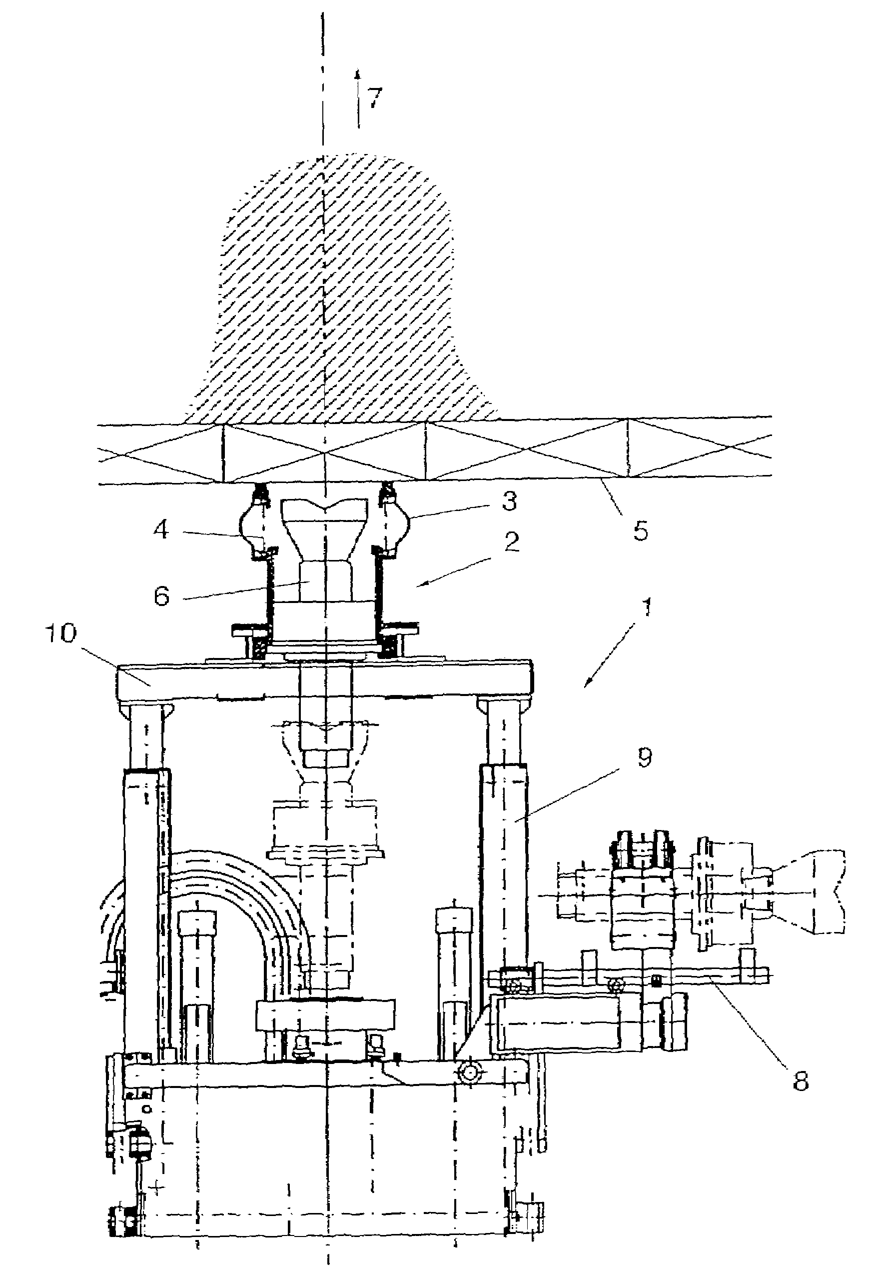
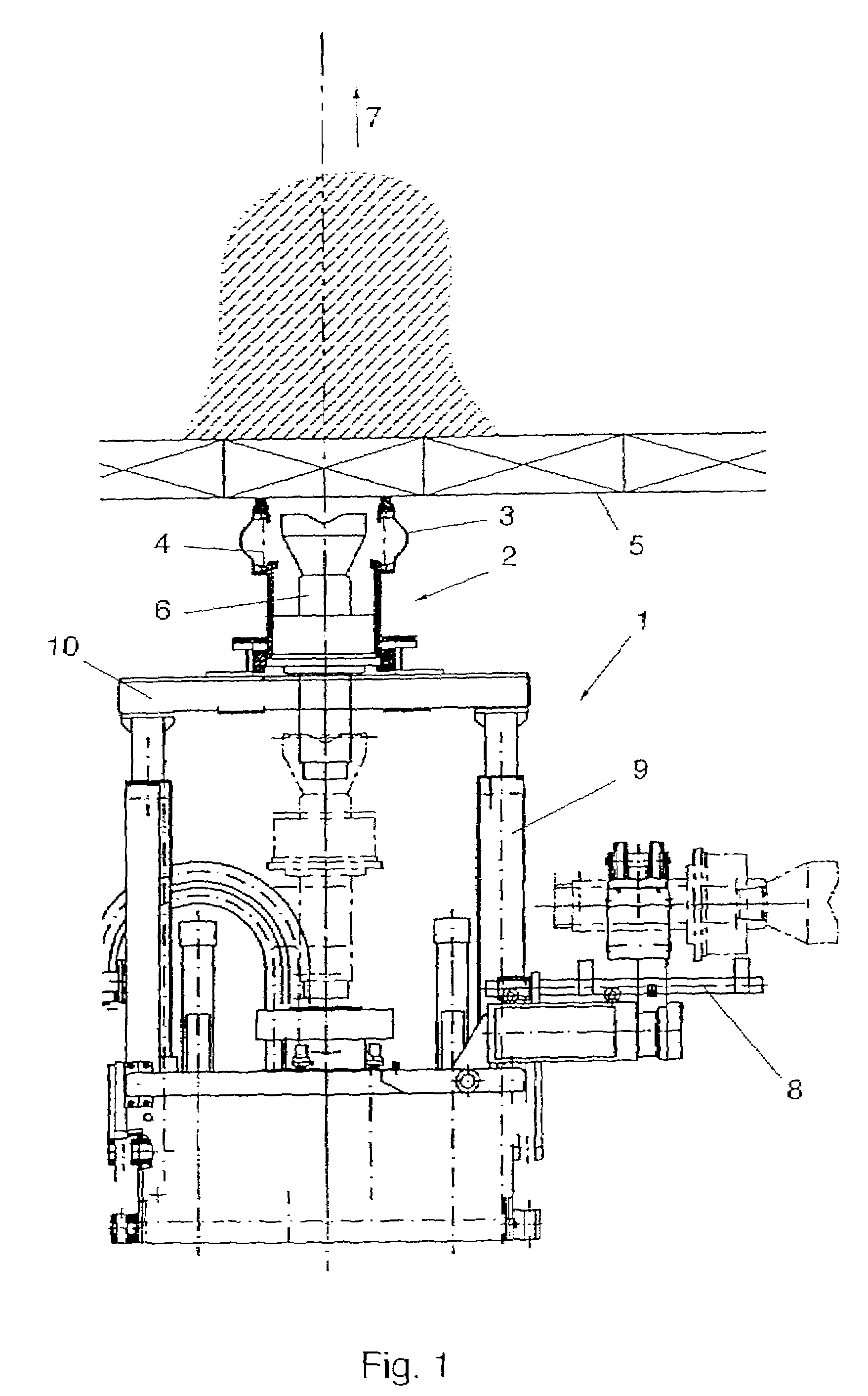
[0016]FIG. 1 schematically elucidates the starting phase of the excavation process extensively described in U.S. Pat. No. 5,380,127. The blow-out preventor 2 is fixed on a drilling frame 1 with an elastic sealing collar 3 being pressed at the lining 5 of the tunnel by means of a helical spring 4 and a drilling tool 6 being connected with the drilling station 1. The drilling tool 6 is then advanced in the sense of arrow 7, i.e., in the axial direction of the bore, whereby short extension pieces are each arranged between the actuator and the drill bit in the drilling station 1. In this phase, the sealing collar 3 safeguards perfect dust sealing relative to the tunnel lining, wherein a manipulator 8 is additionally apparent from the illustration according to FIG. 1, which serves to pivot the drilling tool and the extension rods into the respective positions in the interior of the drilling station. The drilling station 1 comprises hydraulic cylinder-piston units 9 to adjust the height p...


PUM


Abstract

In a device for sealing a bore hole and discharging drill cuttings and stripped excavation material, including a housing adapted to receive sealing elements and an opening capable of being connected to the bore hole, one side wall of the housing is provided with at least one opening for the connection of a haulage duct, wherein the housing end side facing the bore hole is equipped with a lockable, particularly screwable, sealing flange (13) for the detachable connection with a bore hole lining (11). The sealing flange (13) is rotationally and sealingly mounted within the housing and carries projections, in particular an annular brim (15) which is overlapped by a stop (14) of the housing.

Description

BACKGROUND OF THE INVENTION[0001]The invention relates to a device for sealing a bore hole and discharging drill cuttings and stripped excavation material, including a housing adapted to receive sealing elements and an opening capable of being connected to the bore hole, wherein one side wall of the housing is provided with at least one opening for the connection of a haulage duct and the housing end side facing the bore hole is equipped with a lockable, particularly screwable, sealing flange for the detachable connection with a bore hole lining.[0002]Devices of the initially defined kind are used, for instance, for oil drill cuttings with a device of this type being described, for instance, in U.S. Pat. No. 4,529,210. The known devices are also denoted as blow-out preventors. However, when using same in the field of oil-drilling technology, large free spaces are usually accessible above the bore hole such that the known blow-out preventors can be relatively large-structured, having...

Claims


Application Information

Patent Timeline
Patent Type & Authority Patents(United States)
IPC IPC(8): E21B21/015E21B17/00
CPCE21B21/015E21B17/006
Inventor EBNER, BERNHARDWEINBERGER, GERHARDREUMULLER, BRUNOSCHMITKE, BARRY
Owner VOEST ALPINE BERGTECHNIK GMBH
Why Eureka
Try Eureka