Intake device

a technology of intake device and intake chamber, which is applied in the direction of heating type, separation process, application, etc., can solve the problem that no uncombusted fuel is therefore able to escape the combustion chamber, and achieve the effect of reducing flow cross-section, simple assembly and manufacture of the intake device, and good sealing

a technology of intake device and intake chamber, which is applied in the direction of heating type, separation process, application, etc., can solve the problem that no uncombusted fuel is therefore able to escape the combustion chamber, and achieve the effect of reducing flow cross-section, simple assembly and manufacture of the intake device, and good sealing

US7011298B2Active Publication Date: 2006-03-14ANDREAS STIHL AG & CO KG

Image

  • Intake device
  • Intake device
  • Intake device

Examples


Embodiment Construction

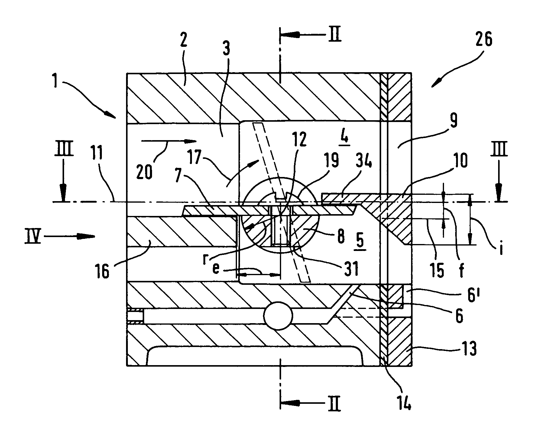
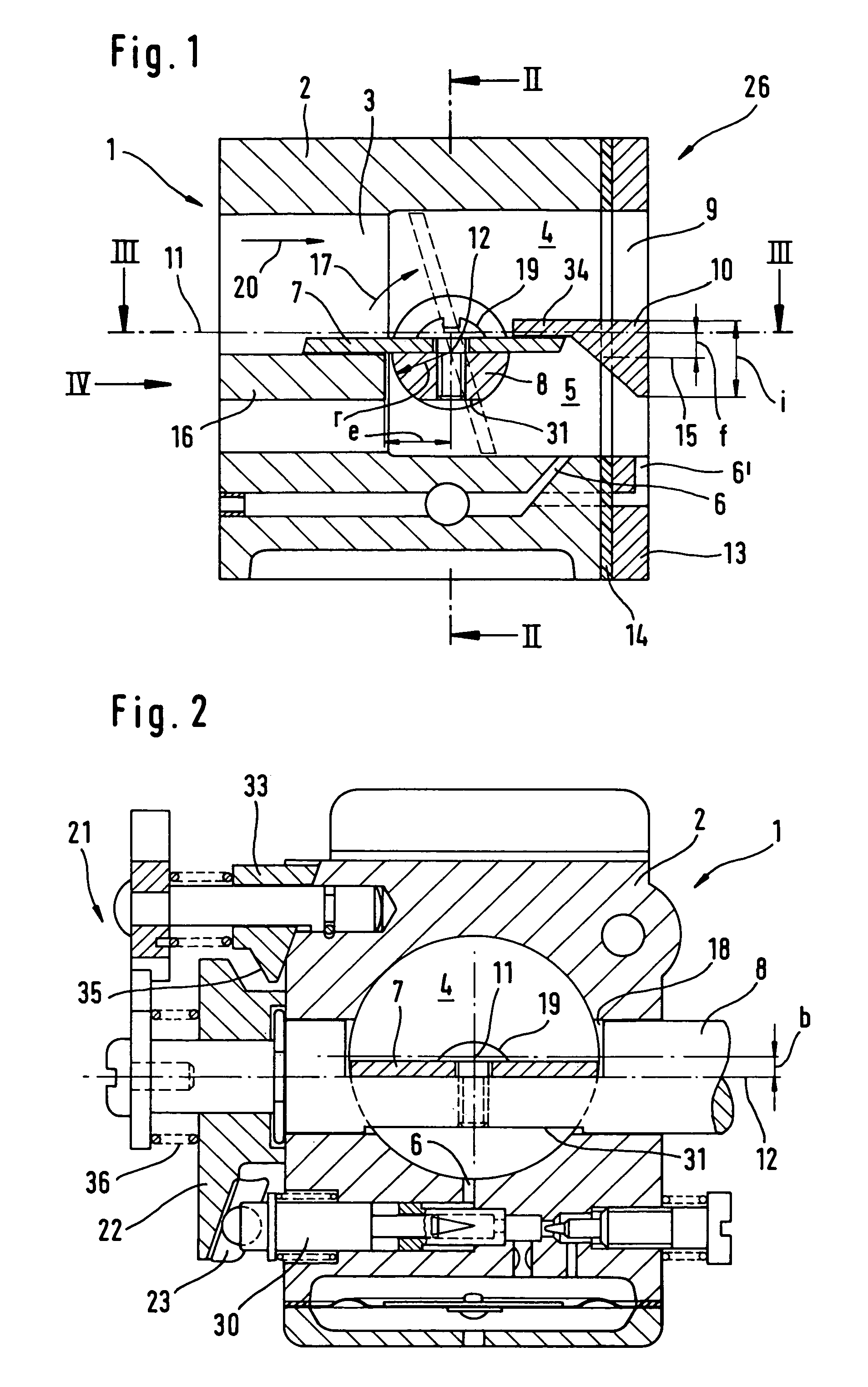
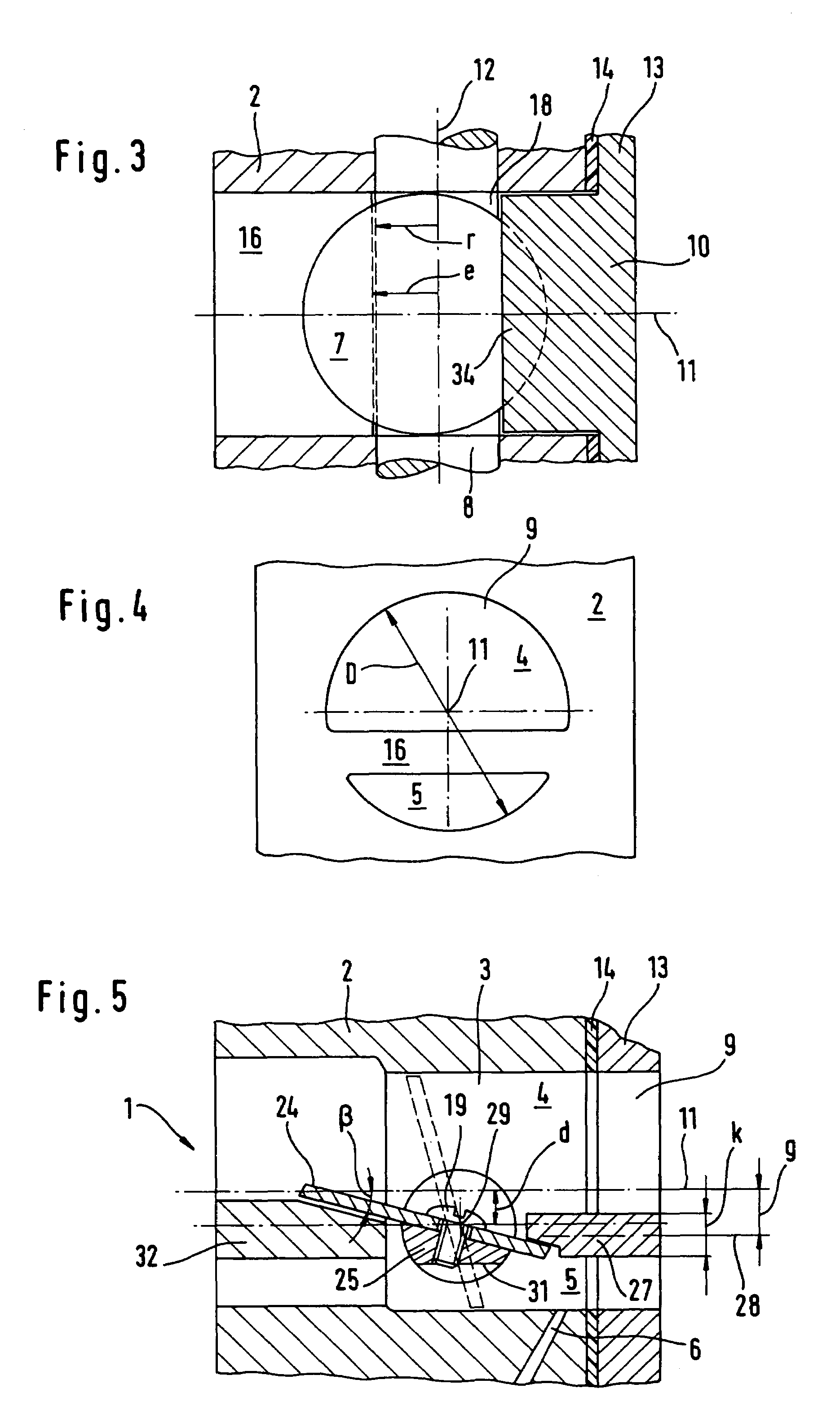
[0023]FIG. 1 shows an aspirating or intake device 26 which has an intake port or channel 9. An intake port section 3 of the intake port 9 is formed in a carburetor 1. The carburetor 1 has a carburetor housing 2 and serves to supply fuel / air mixture and largely fuel-free combustion air to an internal combustion engine. The internal combustion engine is in particular a two-stroke engine, the combustion air serving as scavenging air to separate exhaust gas and the fuel / air mixture which follows it in the combustion chamber. The air passes through the carburetor 1 in the direction of flow 20. An air filter is advantageously positioned upstream of the carburetor 1. A throttle or butterfly valve 7 with a throttle shaft 8 is mounted in the intake port section 3 in such a manner that it is able to pivot. The intake port 9 is divided into an air duct 4 and a mixture duct 5 by a dividing wall 16 upstream of the throttle valve and by a dividing wall 10 downstream of the throttle valve 7. A fue...


PUM

PropertyMeasurementUnit
Fractionaaaaaaaaaa
Fractionaaaaaaaaaa
Fractionaaaaaaaaaa

Abstract

An intake device having an intake channel that includes an intake channel section is provided. A butterfly valve is pivotably mounted in the intake channel section. A dividing wall is disposed downstream of the butterfly valve and divides the intake channel section into an air duct and a mixture duct. The air duct has a flow cross-section that is greater than the flow cross-section of the mixture duct. A fuel jet opens into the mixture duct.

Description

BACKGROUND OF THE INVENTION[0001]The present invention relates to an aspirating or intake device, in particular for the internal combustion engine in an engine-driven tool such as a chain saw or parting-off grinder, etc.[0002]An intake device in which the intake port is divided into one air duct and two mixture ducts is known from EP 1 221 545 A2. To achieve this a dividing wall is provided which extends essentially downstream of the throttle valve and divides the intake port centrically. The flow cross-sections in the air duct and the mixture duct are thus roughly the same size. The largely fuel-free air supplied to the engine through the air duct serves to separate exhaust gases escaping from the combustion chamber of the engine from the fuel / air mixture flowing after them. If too little air is supplied to the internal combustion engine, it is impossible to separate the mixture from the exhaust gases cleanly and uncombusted fuel / air mixture is therefore able to escape from the com...

Claims


Application Information

Patent Timeline
14 Mar 2006
Publication
US7011298B2
IPC
F02M7/24; F02B63/02; F02D9/02; F02D9/10; F02M13/04; F02M17/09
CPC
F02D9/1045; F02M13/046; F02B63/02; F02D9/1025; Y10S261/01; F02D2009/0272; F02M17/09; F02D9/109
Inventors
GERHARDY, REINHARD; GEYER, KLAUS