Surgical instrument with rotary cutting member and quick release coupling arrangement

a surgical instrument and rotary cutting technology, applied in the field of surgical instruments, can solve the problems of uncontrolled operation, unqualified or unqualified tool shafts, and inability to limit the acceptance of non-approved or qualified tool shafts, so as to prevent unwanted movement of the distal end of the dissection tool, inhibit the attachment of dissection tools, and prevent the effect of bone dissection

Active Publication Date: 2006-03-14
MEDTRONIC PS MEDICAL
View PDF36 Cites 112 Cited by
  • Summary
  • Abstract
  • Description
  • Claims
  • Application Information

AI Technical Summary

Benefits of technology

[0011]A potential advantage of the present invention is the provision of a surgical instrument for the dissection of bone and other tissue in which the dissection tool is precisely centered within the surgical instrument.
[0012]Another potential advantage of the present invention is the provision of a surgical instrument for the dissection of bone and other tissue which inhibits attachment of dissection tools that are not designed for operation in the surgical instrument. Still a further aspect of the present invention is the provision of a dissection tool having a coupling end with drive surfaces and at least one longitudinal alignment surface. In one preferred embodiment of the invention, the alignment surface extends internally to the drive surface. In another preferred embodiment the alignment surface is disposed on the external surface of the dissection tool.
[0013]Another potential advantage of the present invention is the provision of a surgical instrument for the dissection of bone and other tissue in which a dissection tool is more securely attach...

Problems solved by technology

Further, in past designs, the coupling mechanism has not included means to limit the acceptance of non-approved tool shafts.
Specifically, non-approved or qualified tool shafts may suffer from a number of problems.
End users may improperly select a tool shaft of the incorrect strength for a given length, select the incorrect diameter, or attempt to utili...

Method used


Image

  • Surgical instrument with rotary cutting member and quick release coupling arrangement
  • Surgical instrument with rotary cutting member and quick release coupling arrangement
  • Surgical instrument with rotary cutting member and quick release coupling arrangement

Examples


Embodiment Construction

[0081]The following description of the preferred embodiments is merely exemplary in nature and is in no way intended to limit the invention, its application, or uses.

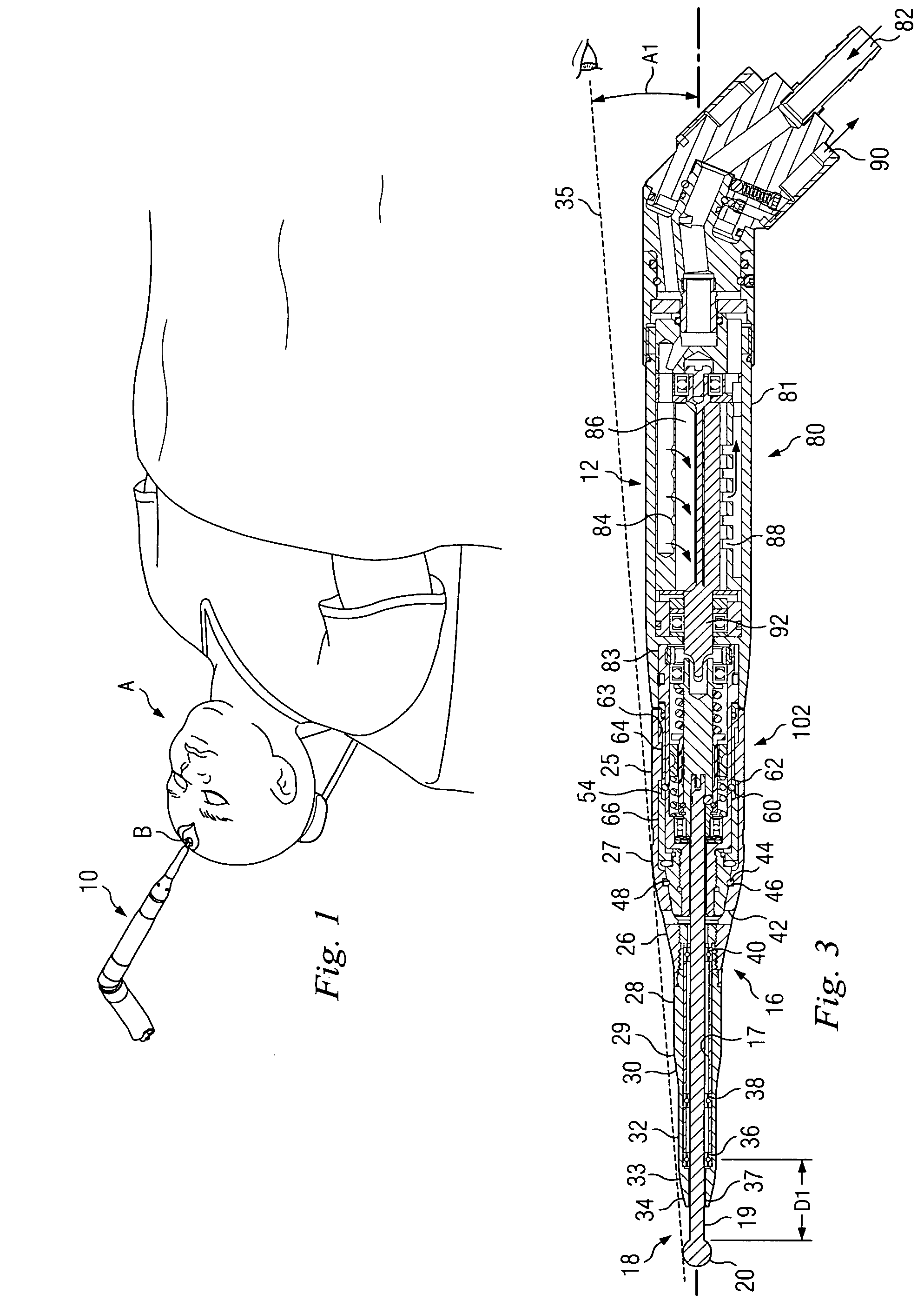
[0082]Referring now to FIG. 1, there is shown a human patient A undergoing a neurological operation. As is common practice, access to the brain or other neurological structures often requires delicate dissection of bone and other tissues B to gain access. By way of example, dissection tool assembly 10 in accordance with one aspect of the present invention is shown being utilized to dissect a portion of patient A's bone and other tissue B adjacent to the surgical access site.

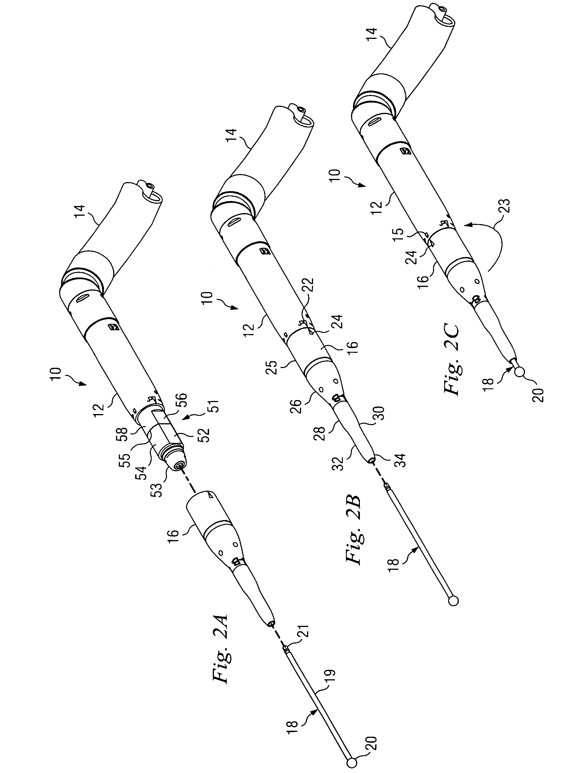
[0083]Referring now to FIGS. 2A–2C, a dissection tool assembly 10 for the dissection of bone or other tissue is illustrated. Dissection tool assembly 10 includes a motor housing 12, coupled to air supply and hose assembly 14 that supplies pressurized air to the motor and vents the low pressure exhaust air away from the surgical site. Dissection tool ...


PUM


Abstract

A surgical instrument for the dissection of bone and other tissue includes a spindle, a dissection tool and a male member carried by the spindle. The spindle includes a cavity. The dissection tool is releasably received in the cavity. The dissection tool extends along an axis and includes a first end and a second end with the first end having a cutting element and a second end having a generally cylindrical cross-section and a centrally located aperture partially extending along the axis. The male member is carried by the spindle and extends into the aperture of the dissection tool. The cavity may define a drive portion and a tool receiving aperture. One or more alignment projections may extend from the drive portion into the tool receiving aperture.

Description

CROSS-REFERENCE TO RELATED APPLICATION[0001]This invention claims priority to U.S. Utility application Ser. No. 10 / 102,762 filed Mar. 21, 2002 and Provisional Application No. 60 / 277,639, filed Mar. 21, 2001, each incorporated herein by reference.FIELD OF THE INVENTION[0002]The present invention generally relates to surgical instruments for use in the dissection of bone and other tissue. More particularly, the present invention relates to a dissection tool and a quick release coupling arrangement for a surgical instrument.BACKGROUND OF THE INVENTION[0003]In various surgical procedures, it is necessary to dissect bone or other tissue. Many conventional surgical instruments used for the dissection of bone or other tissue employ pneumatic or electrical motors to rotate a cutting element. In their most basic form, such surgical instruments comprise a motor portion having a rotary shaft, a dissection tool having a cutting or abrading element that is rotated by the rotating shaft of the mo...

Claims


Application Information

Patent Timeline
IPC IPC(8): A61B17/56A61B17/00A61B17/16A61B17/32
CPCA61B17/162A61B17/32002B23B31/005B23B31/1071B23B31/1074A61B17/1633A61B2017/00477B23B2231/0232A61B2017/320032A61B2017/00482B23B31/1072
Inventor RIEDEL, DANNY C.TIDWELL, DURRELL G.SIMMONS, BRYAN DAVIDESTES, LARRY DALEHILTON, ALLEN P.SHORES, REX WESLEYHENDERSON, JOHN K.SPITLER, JAMES Q.WALKER, MICHELLE L.
Owner MEDTRONIC PS MEDICAL
Why Eureka
Try Eureka