
Reverse-type humeral prosthesis

a humeral prosthesis and reverse-type technology, applied in the field of shoulder prosthesis, can solve the problems of compromising the function of the prosthetic joint, deteriorating the shoulder joint that can accompany a shoulder arthroplasty, and total loss of key constraints that maintain the patency of the joint, so as to achieve the effect of avoiding replacement and removing

Inactive Publication Date: 2006-03-14
DEPUY PROD INC
View PDF33 Cites 142 Cited by
  • Summary
  • Abstract
  • Description
  • Claims
  • Application Information

AI Technical Summary

Benefits of technology

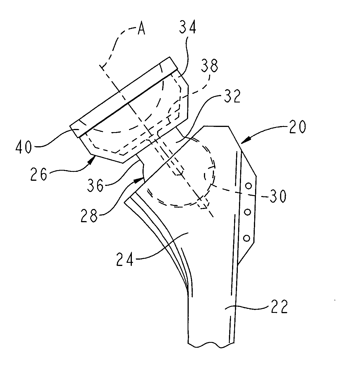
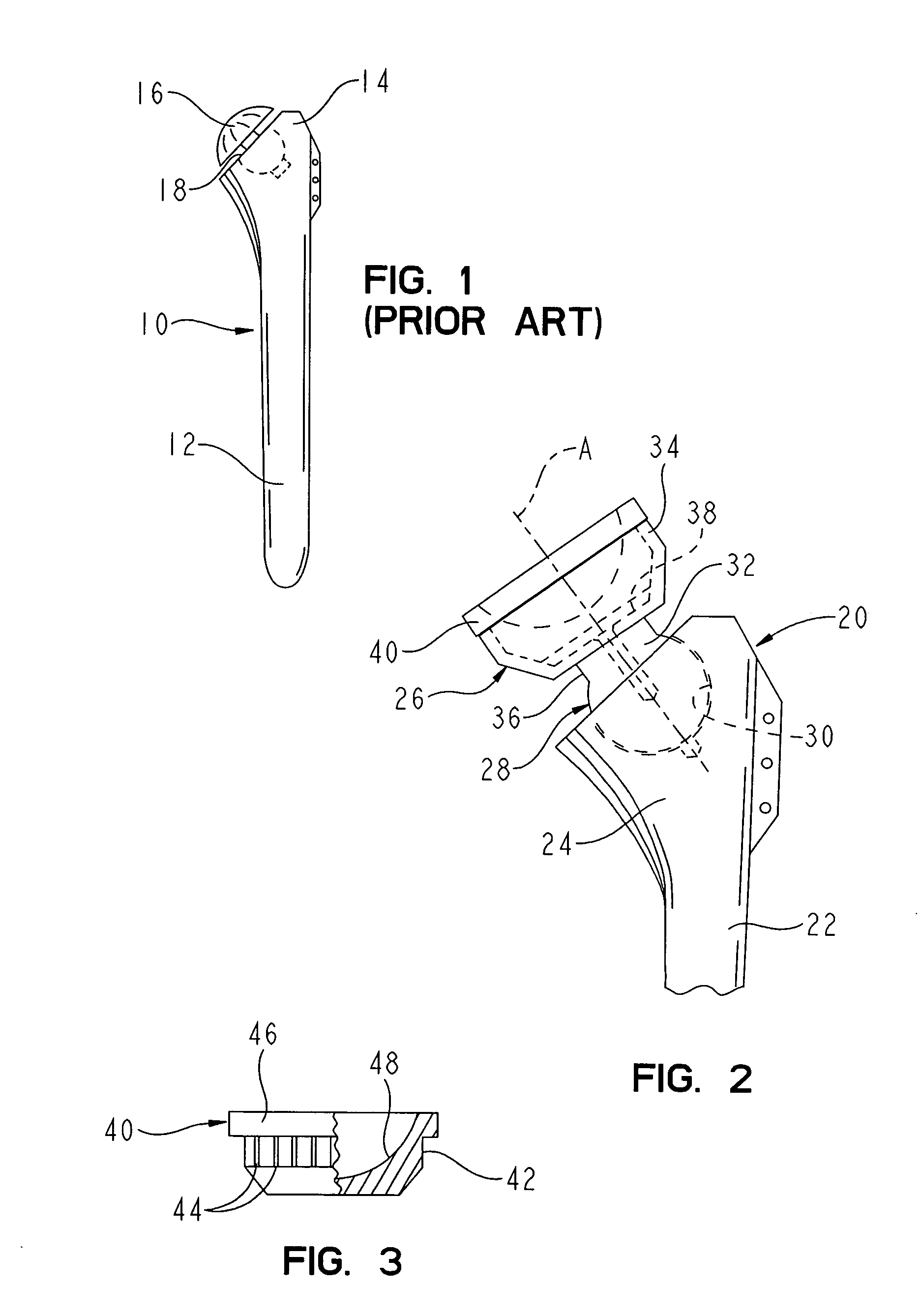
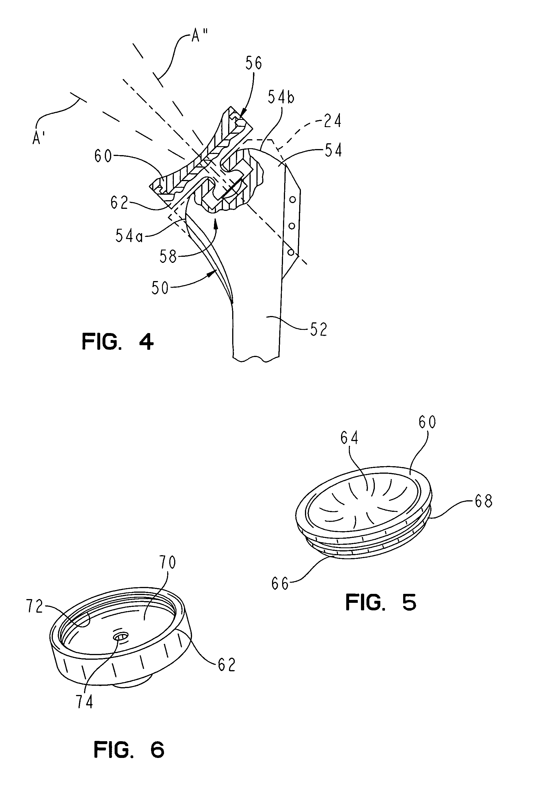
[0009]In one feature of the invention, the articulating component is mounted to the implanted stem so that the component is not engaged within the bone. In a preferred embodiment, the articulating component is situated outside the prepared end of the humerus. In an alternative embodiment, portions of the articulating component can reside within the envelop of the proximal end of the bone without being engaged to the component. Thus, the articulating component can be readily removed and replaced without disturbing the bone. This approach can be particularly useful in a trial procedure.

Problems solved by technology

One problem faced by both the conventional and the modular shoulder prostheses is the deterioration of the shoulder joint that can accompany a shoulder arthroplasty.
For instance, a patient who has undergone shoulder arthroplasty may experience loss of soft tissue and soft tissue strength, which can eventually lead to a total loss of key constraints that maintain the patency of the joint.
This loss of soft tissue and soft tissue strength can allow unnatural joint loads to be produced, which can compromise the function of the prosthetic joint and / or lead to joint pain.
Of course, this surgical procedure is very difficult and invasive, and can place the patient and the shoulder joint at risk.

Method used


Image

  • Reverse-type humeral prosthesis
  • Reverse-type humeral prosthesis
  • Reverse-type humeral prosthesis

Examples


Embodiment Construction

[0029]For the purposes of promoting an understanding of the principles of the invention, references will now be made to the embodiments illustrated in the drawings and described in the following written specification. It is understood that no limitation to the scope of the invention is thereby intended. It is further understood that the present invention includes any alterations and modifications to the illustrated embodiments and includes further applications of the principles of the inventions as would normally occur to one skilled in the art to which this invention pertains.

[0030]The context of the present invention can be understood with reference to a humeral component of a shoulder prosthesis of the prior art. For instance, a humeral implant 10, as shown in FIG. 1, can include a stem 12 configured to be implanted within a bore prepared in the humerus bone. The proximal portion 14 of the stem is at the prepared proximal end of the bone. The proximal portion supports a prostheti...


PUM


Abstract

A humeral component of a shoulder prosthesis includes a stem configured for implantation within the humerus. A reverse articulating component is mounted to the stem by a connection mechanism. The reverse component defines a substantially concave bearing surface. The bearing surface is part of a bearing member that is engaged to a support member that is associated with the connection mechanism. A kit is provided which includes differently configured bearing members and support members to allow intraoperative selection and assembly of an optimum articulating component.

Description

BACKGROUND OF INVENTION[0001]The present invention relates generally to prosthetic joints, and more particularly to a shoulder prosthesis. The invention has specific application with respect to the humeral component of the shoulder prosthesis.[0002]Conventional prostheses for the replacement of the shoulder joint include a segment engaged within the humerus bone and a mating articulating segment associated with the glenoid bone. In the typical shoulder prosthesis, the upper portion of the humerus is replaced by a unitary structure. This structure includes a stem designed to extend downwardly into a bore or cavity formed within the humerus. This stem is secured within the bone by bone cement or through the use of coatings configured to promote bone ingrowth to secure the stem in place. Again with the conventional prosthesis, the stem is attached to a body portion that is designed to replace portions of the humerus at the anatomical neck of the bone. A generally spherical head portion...

Claims


Application Information

Patent Timeline
IPC IPC(8): A61F2/40A61B17/56A61F2/00A61F2/02A61F2/30A61F2/46
CPCA61F2/4014A61F2/40A61F2310/00011A61F2/4059A61F2/4684A61F2002/30112A61F2002/30332A61F2002/30354A61F2002/30364A61F2002/30367A61F2002/30373A61F2002/30378A61F2002/30403A61F2002/30487A61F2002/30495A61F2002/305A61F2002/30507A61F2002/30512A61F2002/30538A61F2002/30574A61F2002/30604A61F2002/30616A61F2002/30772A61F2002/30774A61F2002/30822A61F2002/30884A61F2002/30902A61F2002/4018A61F2002/4022A61F2002/4029A61F2002/4044A61F2002/4051A61F2002/4062A61F2002/4631A61F2002/4638A61F2220/0025A61F2220/0033A61F2230/0004A61F2250/0006
Inventor BALL, ROBERT J.ONDRLA, JEFFREY M.GODEST, ANNE-CELINE
Owner DEPUY PROD INC
Learn More