

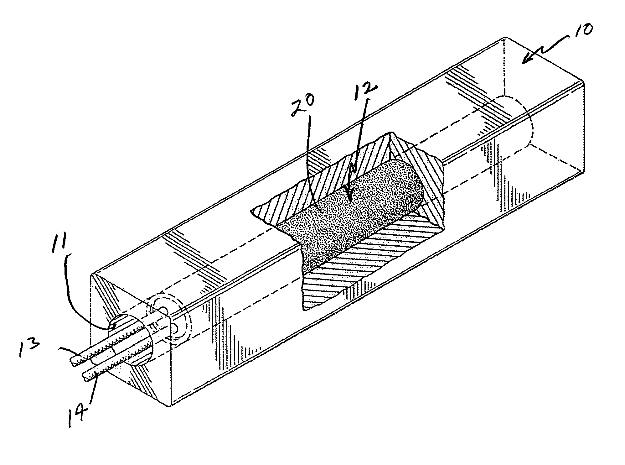
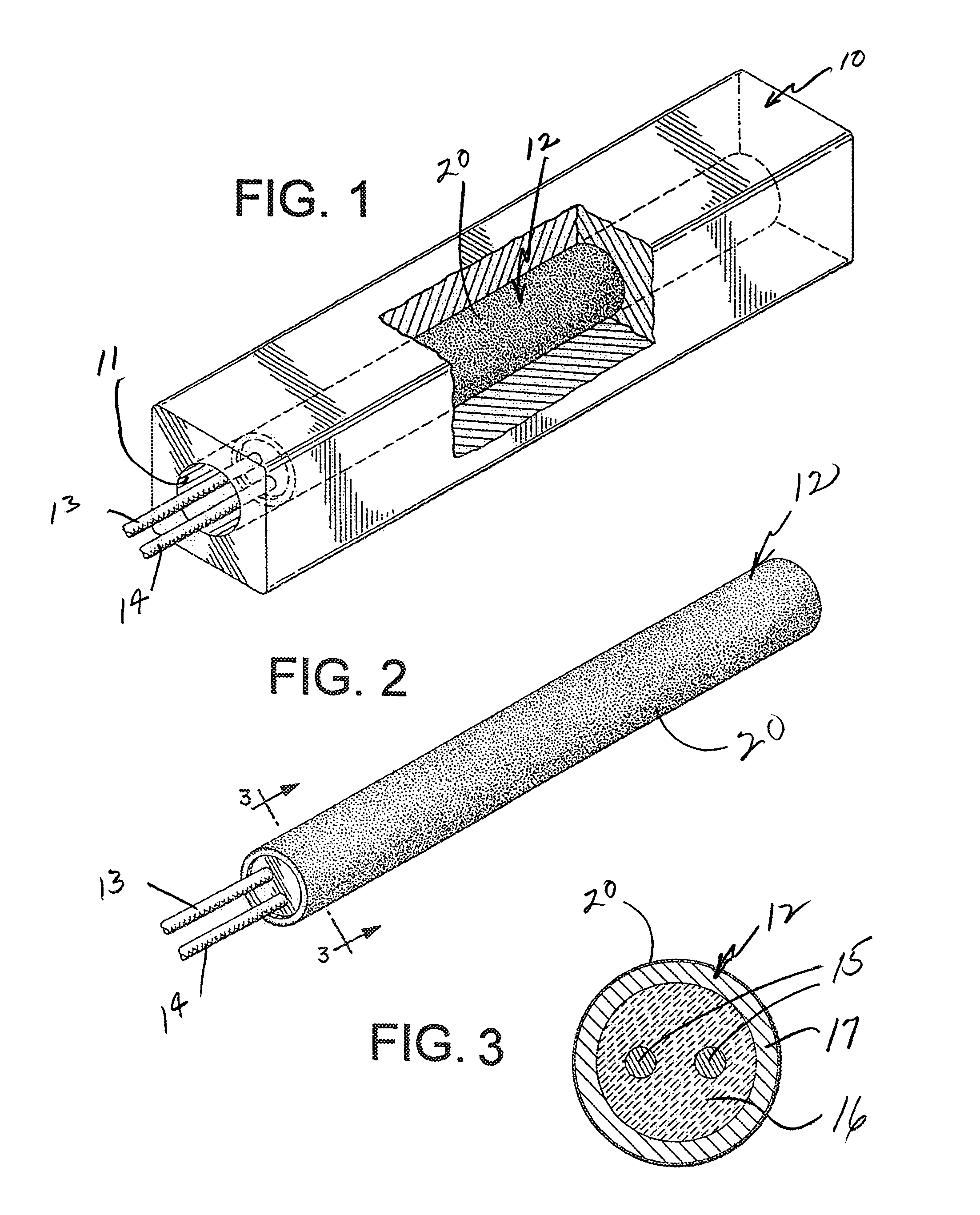
Cartridge heater with a release coating
a technology of cartridge heater and release coating, which is applied in the field of cartridge heaters, can solve the problems of high coating temperature, difficult removal of cartridge heater from bore holes, and damage to the heater as well as the device in which it is used, and achieves the effect of facilitating curing
- Summary
- Abstract
- Description
- Claims
- Application Information
AI Technical Summary
Benefits of technology
Problems solved by technology
Method used
Image

Examples
example 1
[0032]The two heaters, one with the coating and one without, were mounted in the test block. The block was set at an ambient temperature and voltage applied to the block to be heated to 725° F. A thermocouple was centered on the length of the block as well as being centered on the width of the block. The block was cycled ten times at 725° F. temperature and then brought down to 180° F. The heater with the coating was rotatable while the heater without the coating was not rotatable.
example 2
[0033]Again, with one heater with the coating applied to it and one with no coating applied to it and mounted in the test block Voltage was applied to the heaters at 180° F. and was brought up to 725° F. This test also included a thermocouple as in the first example. Like Example 1, the heaters were cycled ten times at 725° F. temperature. Then the rotation test was again used and the results were the same where the coated heater rotated easily and the non-coated heater would not rotate.
example 3
[0034]This test did not include the use of any thermocouple to control the temperature. Again, one heater with a coating applied to it and one heater with no coating applied to it were inserted in the test block bore holes. The temperature was allowed to run wild and the block reached a temperature of 1600° F. within the first hour that power was applied to the heaters. The heaters ran for about six hours at that temperature and the block did not exceed the 1600° F. temperature. After a period of six hours the test block was allowed to cool down to ambient temperature and the rotation test was again made. Again, the coated heater was rotatable, while the uncoated heater was not rotatable. Further, the coated heater was removable with little difficulty, but the non-coated heater was not removable.
[0035]In view of the foregoing, it should be appreciated that the present invention provides a heater with a sold film lubricant coating as a release coating that is capable of being cured w...
PUM
 Abstract
Description
Claims
Application Information