
Portable device for measuring a position, a shape, and a size of an object

a technology for measuring objects and portable devices, applied in the direction of measuring devices for acceleration/shock, measuring transmission units, instruments, etc., can solve the problems of inability to access the transmission unit and/or the receiving unit from outside the housing, affecting the accuracy of the measurement, and the production of conventional devices is relatively demanding and expensive. , to achieve the effect of compact siz

Active Publication Date: 2006-03-14
INOS AUTOMATIONSSOFTWARE
View PDF6 Cites 5 Cited by
  • Summary
  • Abstract
  • Description
  • Claims
  • Application Information

AI Technical Summary

Benefits of technology

[0016]A further advantage is the miniaturization of the device due to particularly compact construction.
[0035]The cover flaps can advantageously be pivoted into and out of the optical path. A pivot axis or pivot motion of the cover flaps preferably extends parallel to an optical axis of the transmission or receiving unit. The cover flaps are preferably moved by electromotors. Electromotors are particularly advantageous due to their compact size and the same power source (electricity rather than gas or liquid) can be used as for the other sensor elements. A pneumatic or hydraulic drive of the cover flaps is also feasible, in particular when the flaps are larger.

Problems solved by technology

The housing is then closed and access to the transmission unit and / or the receiving unit from outside the housing is no longer possible.
This requires production of a plurality of different embodiments of the device for the various applications which makes production of the conventional devices relatively demanding and expensive.
This results in considerable costs for purchase, storage and maintenance of the conventional devices.
Even when the measuring distance must be changed for a subsequent application, the sensor cannot be simply adjusted, rather must be entirely replaced.
This results in substantial costs for the end user.

Method used


Image

  • Portable device for measuring a position, a shape, and a size of an object
  • Portable device for measuring a position, a shape, and a size of an object
  • Portable device for measuring a position, a shape, and a size of an object

Examples


Embodiment Construction

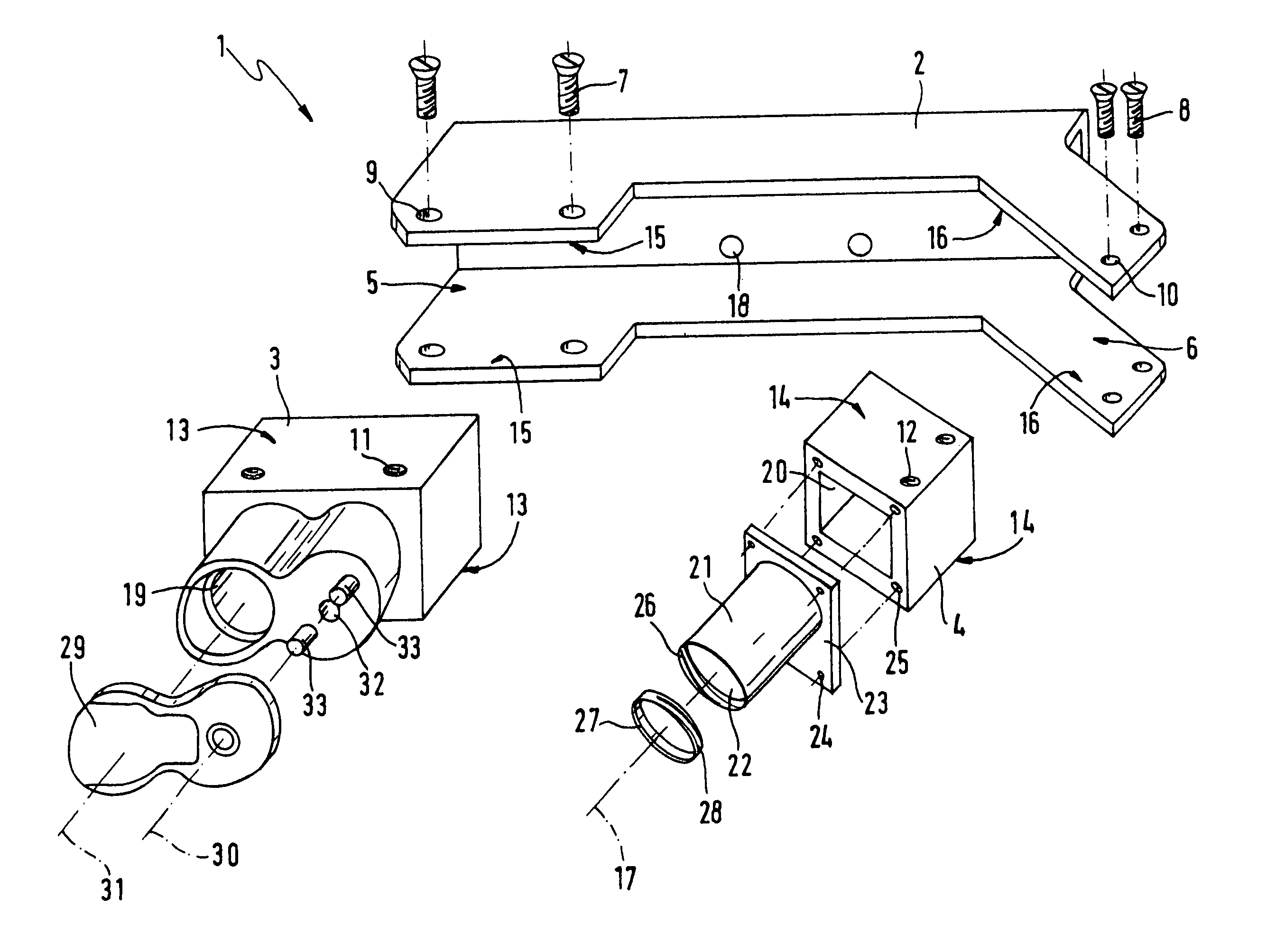
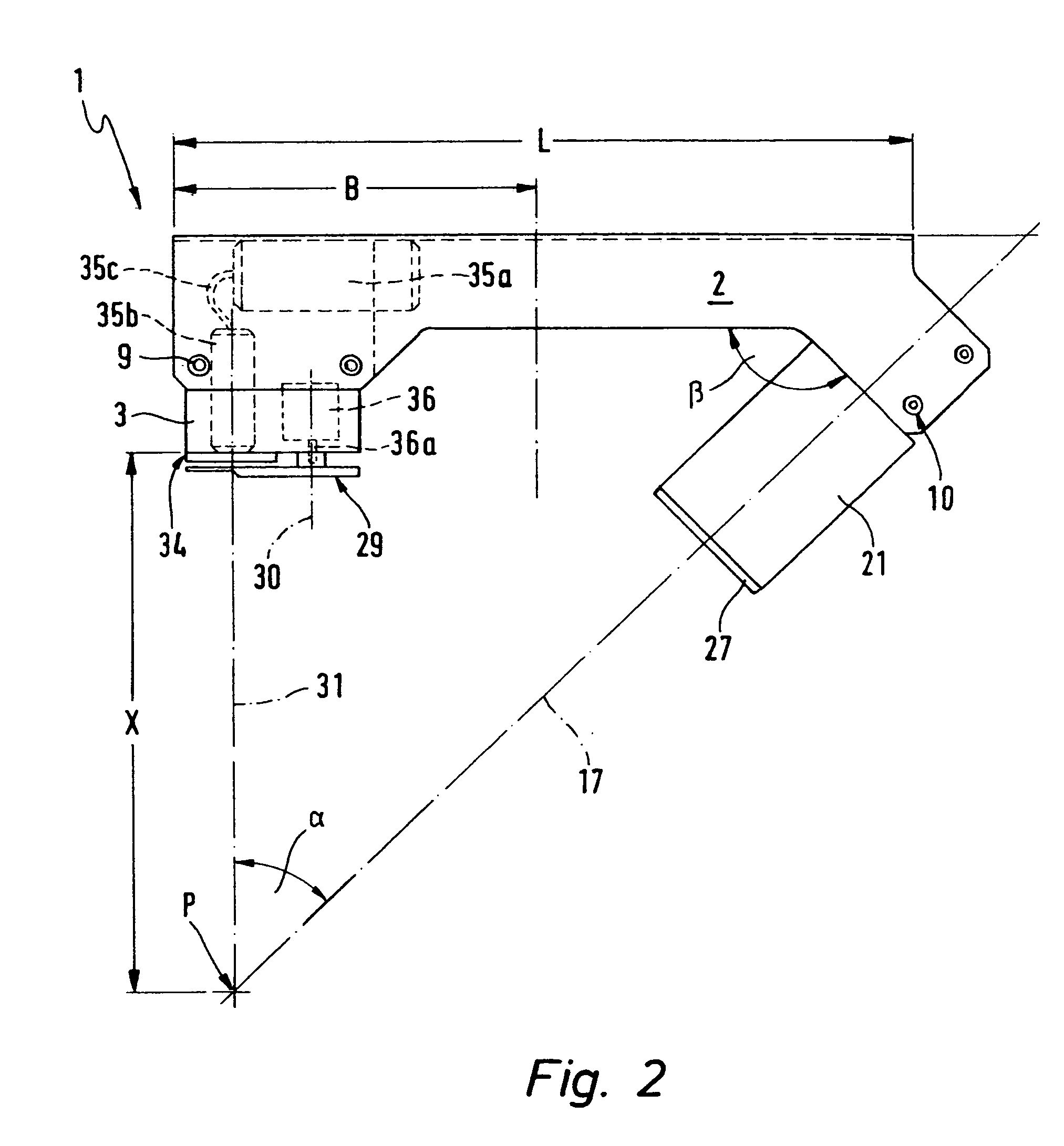
[0041]FIG. 1 shows an embodiment of the inventive portable device for measuring the position and / or size of an object, referred to in its entirety with 1. In the embodiment of FIG. 1, the device 1 has a carrier element 2 and a first holding element 3 for a transmission unit and a second holding element 4 for a receiving unit. Portable in the sense of the invention means that the device 1 is relatively small and can be guided either manually, e.g. via a measuring arm (distributed by the company Faro Technologies, Inc., Lake Mary, Fla., USA) or by an industrial robot. Towards this end, the device 1 is mounted via suitable openings 18 in the carrier element 2 to the distal end of the measuring arm or a robot arm of the industrial robot.

[0042]The transmission unit produces and transmits visible radiation towards the object to be measured. The receiving unit receives the radiation imaging the object. The radiation used to measure the object may be visible to the human eye. Radiation whic...


PUM


Abstract

The invention concerns a portable device (1) for measuring the position, shape and / or size of an object. The device comprises a carrier element (2), at least one transmission unit for generating and transmitting visible radiation towards the object and at least one receiving unit for receiving the radiation imaging the object. The transmission unit and receiving unit are mounted in a defined position relative to each other on the carrier element (2). Modular construction provides high variability of the device (1) so that it can be used flexibly for various applications. In particular, the transmission unit is mounted to a first holding element (3) and the receiving unit to a second holding element (4), wherein the holding elements (3, 4) can be introduced together with the transmission unit or receiving unit from outside the carrier element (2) to predeterminable mounting positions (5, 6) of the carrier element (2) and be mounted there using mounting means (7, 8) which can be accessed from outside of the carrier element (2).

Description

[0001]This application claims Paris Convention priority of DE 103 11 247.2 filed Mar. 14, 2003 the complete disclosure of which is hereby incorporated by reference.BACKGROUND OF THE INVENTION[0002]The present invention concerns a portable device for measuring a position, a shape and / or a size of an object. The device has a carrier element, a transmission unit for generating and transmitting visible radiation towards the object and a receiving unit for receiving the radiation imaging the object. The transmission unit and the receiving unit are mounted to the carrier element in a defined position relative to each other.[0003]Portable in the sense of the present invention means that the device is relatively small and can be guided either manually e.g. via a measuring arm, a coordinate measuring machine or by an industrial robot, and introduced to the object to be measured. Measuring arms are distributed e.g. by the company Faro Technologies, Inc., Lake Mary, Fla., USA. Coordinate measu...

Claims


Application Information

Patent Timeline
IPC IPC(8): G01B11/03G01B11/00G01B11/24
CPCG01B11/24G01B11/00
Inventor TASSAKOS, CHARALAMBOSDEMOPOULOS, ANDREAS
Owner INOS AUTOMATIONSSOFTWARE
Learn More