Cuttable illumination device

a technology of illumination device and cutting device, which is applied in the direction of semiconductor lamp usage, display means, lighting and heating apparatus, etc., can solve the problems of difficult to overcome, difficult to initial handle, install and/or replace, and high cost of neon lighting package and ship

Active Publication Date: 2006-03-14
LUMINII PURCHASER LLC
View PDF6 Cites 57 Cited by
  • Summary
  • Abstract
  • Description
  • Claims
  • Application Information

AI Technical Summary

Benefits of technology

[0016]In yet another aspect of the invention, the cuttable illumination device further has a waveguide member having a rod-like shape, a predetermined length, a lateral light-receiving surface, and a lateral light-emitting surface. The waveguide member is composed of a material that has both optical waveguide and light-scattering properties. The light-receiving surface of the waveguide member is positioned adjacent to the LEDs such that light from the LEDs entering the waveguide will be scattered causing a light intensity pattern that appears substantially uniform along the light-emitting surface of the waveguide member. Additionally, the device may further have a housing positioned below and extending along the waveguide member, where the housing encloses the circuit board, the LEDs, and the Zener diode. Still further, the housing may have a pair of sidewalls and a floor portion connecting the sidewalls where the sidewalls and floor portion have reflective internal surfaces. Lastly, even further still, the position of the circuit board, the LEDs, and the Zener diode within the housing may be maintained by filling the housing with a potting material.

Problems solved by technology

Because of the fragility and heavy weight, primarily due to its supporting infrastructure, neon lighting is expensive to package and ship.
Moreover, it is extremely awkward to initially handle, install, and / or replace.
However, the twin attributes of neon lighting, uniformity and brightness, have proven to be difficult obstacles to overcome as such attempts to simulate neon lighting.
While the tubing may be lit by such arrangement, the light transfer efficiencies with such an arrangement is likely to result in a “glowing” tube having insufficient intensity to match that of neon lighting.
The use of point light sources such as LEDs may provide intense light that rival or exceed neon lighting, but when arranged in arrays, lack the uniformity needed and unfortunately provide alternate high and low intensity regions in the illuminated surfaces.
Attempts to smooth out the light have resulted in lighting that has unacceptably low intensity levels.
While it is important that the disadvantages of neon lighting be avoided (for example, weight and fragility), an illumination device would have little commercial or practical value if the proper light uniformity and intensity could not be obtained.
However, once the point light sources and associated circuit elements, including any circuit substrate or circuit board, have been positioned in a housing continuous with the waveguide, any such cutting or trimming would necessarily cut off some point light sources and associated circuit elements.
This could potentially cause the remaining portion of the device to stop functioning or perform radically different from the desired characteristics.

Method used


Image

  • Cuttable illumination device
  • Cuttable illumination device
  • Cuttable illumination device

Examples


Embodiment Construction

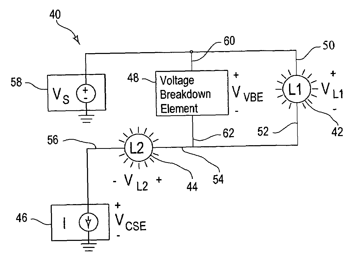
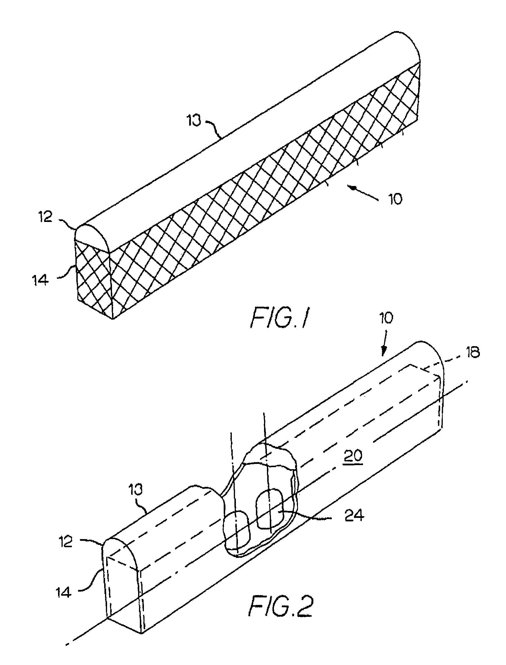
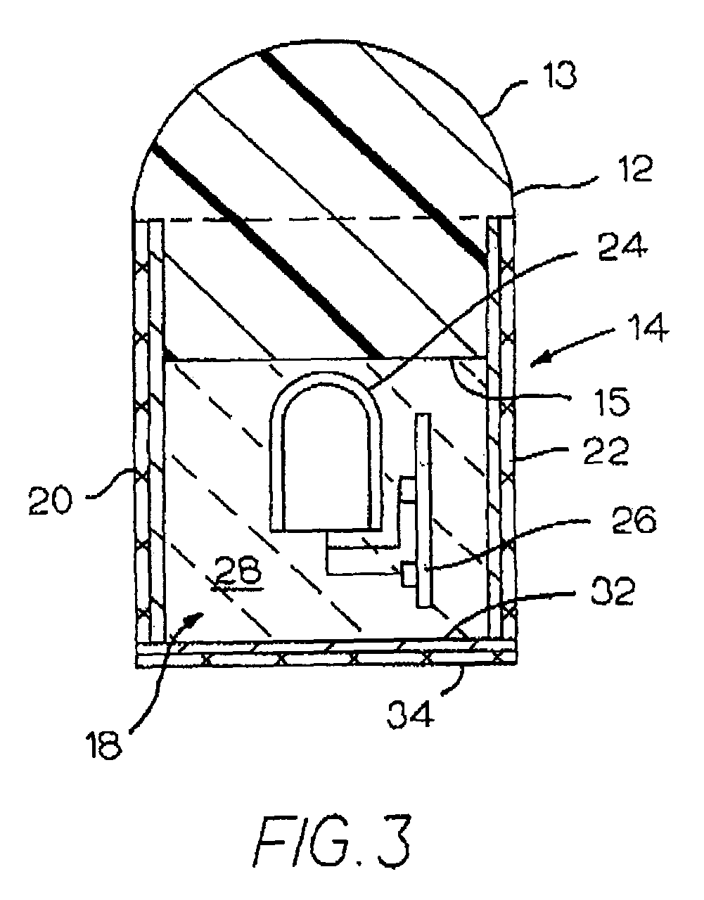
[0031]The present invention is a cuttable illumination device for simulating neon lighting using a string of point light sources and having a construction that allows for the cutting or trimming of the device to a desired length. The preferred illumination device uses a high-intensity, but dimensionally small, light source together with an element that acts both as an optical waveguide and light scattering member, thus permitting light to exit laterally out of its surface. As described in related U.S. Pat. No. 6,592,238, which has been incorporated in its entirety by reference, this element is referred to as a “leaky waveguide.” By placing the light source contiguous to such a leaky waveguide in a specific manner so as to cause the waveguide to uniformly glow over its lateral surface, applicants are able to obtain an illumination device that rivals or surpasses the uniform glow of neon tubing. A combination of circuit elements allows cutting or trimming of the device to a desired le...


PUM


Abstract

A cuttable illumination device has a first lamp, a second lamp, a current source element, and a voltage breakdown element connected such that the first lamp may be removed from the device without affecting the function and performance of the remaining portion of the illumination device. Additional lamps may be added to the device in conjunction with additional voltage breakdown elements to form a string of lamps where any number of lamps may be removed without affecting the function and performance of the remaining portion of the device. The device may have a waveguide member and a housing, creating a cuttable illumination device for simulating neon lighting.

Description

CROSS-REFERENCE TO RELATED APPLICATIONS[0001]The present application claims priority to U.S. Provisional Application Ser. No. 60 / 458,154 filed Mar. 27, 2003, the entire disclosure of which is incorporated herein by reference. This application also relates to U.S. Utility patent application Ser. No. 09 / 982,705 filed Oct. 15, 2001, now U.S. Pat. No. 6,592,238, issued Jul. 15, 2003, entitled Illumination Device for Simulating Neon Lighting, the entire disclosure of which is incorporated herein by reference.BACKGROUND OF THE INVENTION[0002]The present invention relates to a cuttable illumination device for simulating neon lighting, an illumination device ideally adapted for lighting, signage and advertising uses.[0003]Neon lighting, which is produced by the electrical stimulation of the electrons in the low-pressure neon gas-filled glass tube, has been a main stay in advertising and for outlining channel letters and building structures for many years. A characteristic of neon lighting i...

Claims


Application Information

Patent Timeline
Patent Type & Authority Patents(United States)
IPC IPC(8): H05B37/00
CPCH05B33/0803H05B33/0809H05B33/083Y10S362/806Y10S362/80H05B45/345H05B45/395H05B45/48Y02B20/30
Inventor CHAMBERS, JOE A.DOMINICK, JOHN R.ERIKSSON, ERIC OLAV
Owner LUMINII PURCHASER LLC
Why Eureka
Try Eureka