Civil aviation passive coherent location system and method

a technology of coherent location and civil aviation, applied in direction finders using radio waves, instruments, reradiation, etc., can solve the problems of large regulatory procurement and compliance costs, high life-cycle costs of conventional civil aviation radar systems, and the inability to operate current civil aviation radar systems on a temporary or mobile basis, so as to quickly establish an accurate track for the plane

Inactive Publication Date: 2006-03-14
LOCKHEED MARTIN MISSION SYST
View PDF67 Cites 48 Cited by
  • Summary
  • Abstract
  • Description
  • Claims
  • Application Information

AI Technical Summary

Benefits of technology

[0011]The present invention also may be used to monitor the airspace of a predetermined location using ambient transmissions from at least one uncontrolled transmitter and using initial position information relating to an object approaching the predetermined location. This initial ...

Problems solved by technology

A number of conventional civil aviation radar systems have particularly high life-cycle costs due to the initial cost and the maintenance cost of the radar system.
Furthermore, because conventional civil aviation radar systems typically broadcast electromagnetic signals, which is a regulated activity, extensive regulatory procurement and compliance costs are associated with operating current civil aviation radar systems.
Additionally, extensive physic...

Method used


Image

  • Civil aviation passive coherent location system and method
  • Civil aviation passive coherent location system and method
  • Civil aviation passive coherent location system and method

Examples


Embodiment Construction

[0020]Reference will now be made in detail to the preferred embodiment of the present invention, examples of which are illustrated in the drawings.

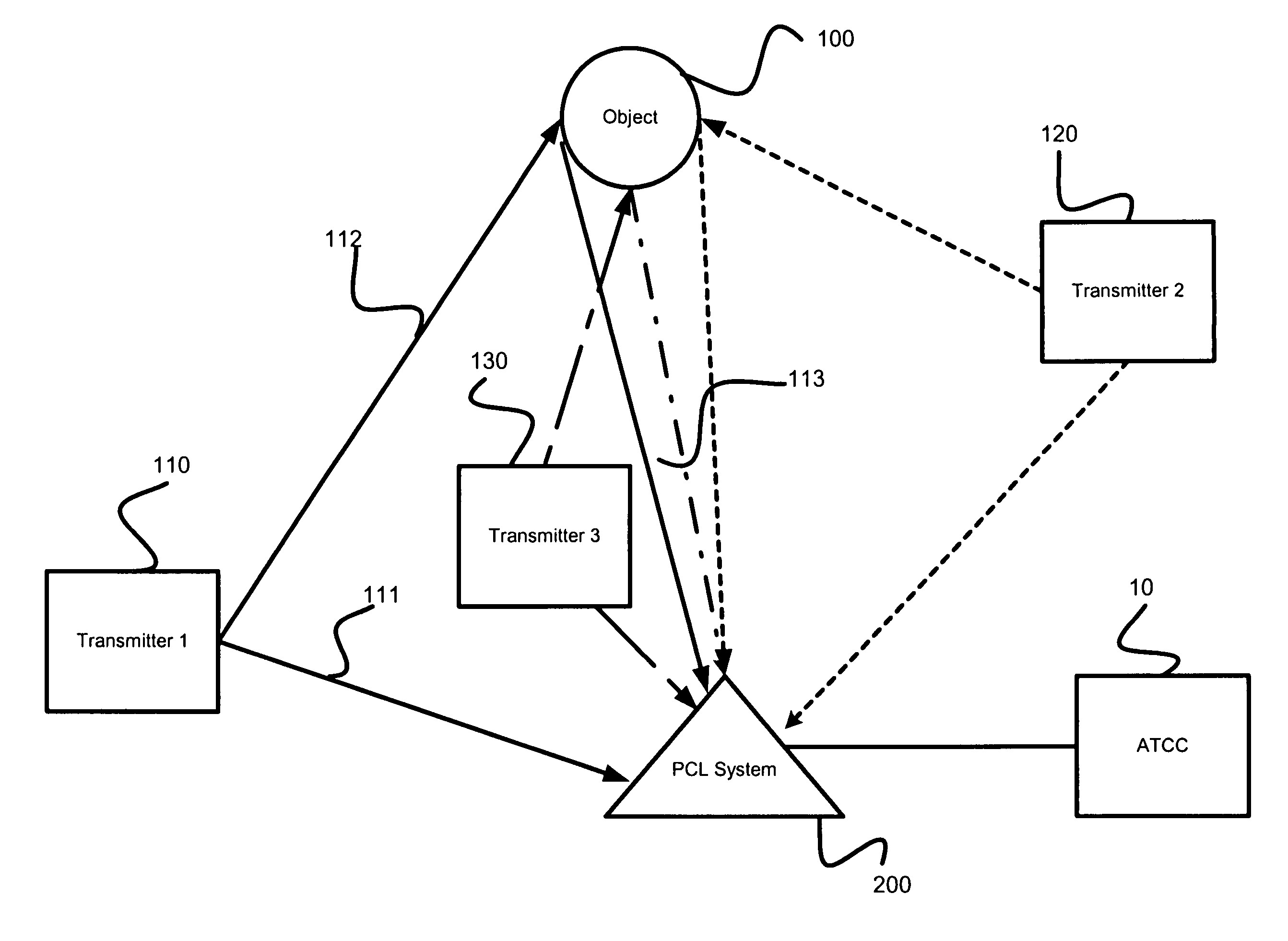
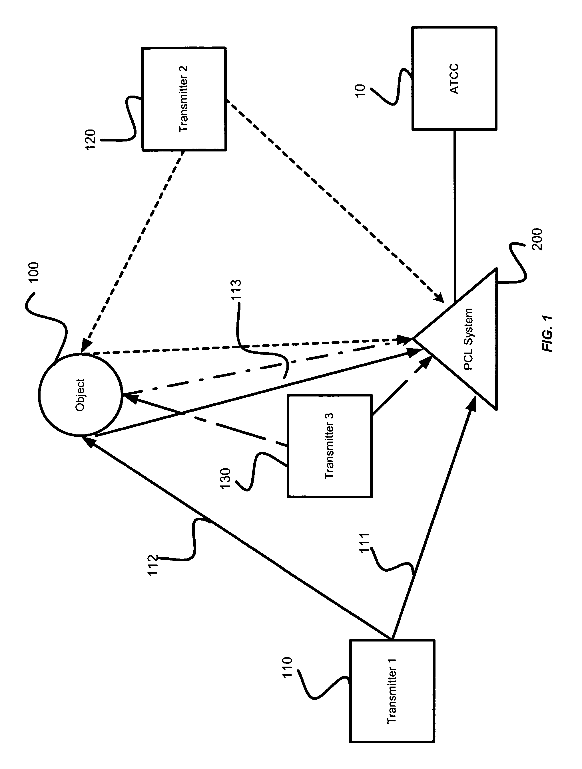
[0021]FIG. 1 illustrates a diagram of a plurality of transmitters, an object, and a PCL system in accordance with an embodiment of the present invention. In a preferred embodiment, a PCL system 200 receives transmissions from a plurality of uncontrolled transmitters 110, 120, and 130. The uncontrolled transmitters 110, 120, and 130 may include radio and television broadcast stations, national weather service transmitters, radionavigational beacons (e.g., VOR), and transmitters supporting current and planned airport services and operations (e.g., automatic dependant surveillance-broadcast), any of which may or may not be under the operational control of the entity controlling PCL system 200. Additionally, PCL system 200 may use signals from transmitters operated by operationally independent entities. More preferably, the signals are freque...


PUM


Abstract

A civil aviation passive coherent location system and method is disclosed. A receiver subsystem receives reference transmissions from an uncontrolled transmitter. The receiver subsystem also receives scattered transmissions originating from the uncontrolled transmitter and scattered by an airborne object. The received transmissions are compared to determine measurement differentials, such a frequency-difference-of-arrival, a time-difference-of-arrival and an angle of arrival. From the measurement differentials, an object state estimate is determined. A previous state estimate may be updated with the determined state estimate. Processing subsystems determine the measurement differentials and state estimates.

Description

CROSS REFERENCE TO RELATED APPLICATIONS[0001]This present application claims benefit of U.S. Provisional Application No. 60 / 241,738 for CIVIL AVIATION PASSIVE COHERENT LOCATION METHOD AND SYSTEM, filed Oct. 20, 2000, which is hereby incorporated by reference.BACKGROUND OF THE INVENTION[0002]1. Field of the Invention[0003]The present invention relates to a passive coherent location (“PCL”) system and method, and more particularly to a PCL system and method for use in an aviation environment, such as civil aviation.[0004]2. Description of Related Art[0005]A number of conventional civil aviation radar systems have particularly high life-cycle costs due to the initial cost and the maintenance cost of the radar system. Furthermore, because conventional civil aviation radar systems typically broadcast electromagnetic signals, which is a regulated activity, extensive regulatory procurement and compliance costs are associated with operating current civil aviation radar systems.[0006]Additio...

Claims


Application Information

Patent Timeline
IPC IPC(8): G08B21/00B64F1/36G01S5/12G01S13/00G01S13/46G01S13/50G01S13/91G01S13/933G01S19/48G08G5/00G08G5/04
CPCG01S5/12G01S13/003G01S13/9303G01S13/933G05D1/00
Inventor BAUGH, KEVIN W.LODWIG, RICHARDBENNER, ROBERT
Owner LOCKHEED MARTIN MISSION SYST
Why Eureka
Try Eureka