Video signal processing method and apparatus

a video signal and processing method technology, applied in the field of video signal processing methods and apparatuses, can solve problems such as method by, cross color interference, and harmful influences, and achieve the effect of effectively eliminating cross color interferen

Inactive Publication Date: 2006-03-14
PANASONIC CORP
View PDF14 Cites 9 Cited by
  • Summary
  • Abstract
  • Description
  • Claims
  • Application Information

AI Technical Summary

Benefits of technology

[0023]According to a 14th aspect of the present invention, in the video signal processing apparatus of the 12th aspect, the gain adjuster changes the gain of the output of the second subtracter to one-half when noises are detected by the noise detector, and changes the gain to 0 when no noise is detected by the noise detector. Therefore, cross color interferences can be effectively eliminated from a component video signal having demodulated color-difference signals.
[0024]According to a 15th aspect of the present invention, there is provided a video signal processing method by which dot crawls and time-axis noises are eliminated from luminance signal components of a component video signal, comprising steps of: extracting a first predetermined frequency component from the luminance signal components in three-dimensional frequency space; eliminating a second predetermined frequency component from the luminance signal components according to the size of the first predetermined frequency component when elimination of the dot crawls is designated; and eliminating minute-level components varying in a temporal direction when elimination of the time-axis noises is designated. Therefore, one of the dot crawls and the time-axis noises, or both of these can be effectively eliminated.
[0025]According to a 16th aspect of the present invention, in the video signal processing method of the 15th aspect, the first predetermined frequency component is extracted by filtering the luminance signal components in a horizontal direction with a filter having a pass-band of 3.58 MHz, and further filtering the signal components in a temporal direction with a filter having a pass-band of 15 Hz. Therefore, pixels in which dot crawls occur can be specified, and one of the dot crawls and the time-axis noises or both of these can be effectively eliminated.
[0026]According to a 17th aspect of the present invention, there is provided a video signal processing method by which cross color interferences and time-axis noises are eliminated from color-difference signal components of a component video signal, comprising steps of: eliminating minute-level components varying in a temporal direction of the color-difference signal components when elimination of the time-axis noises is designated; obtaining a difference value of the color-difference signal components between the present frame and an immediately preceding frame when elimination of the cross color interferences is designated; extracting a predetermined frequency component of luminance signal components of the component video signal; obtaining a difference value of the luminance signal components between the present frame and the immediately preceding frame; deciding that the cross color interferences are occurring when the absolute value of the difference value of the color-difference signal components between the present frame and the immediately preceding frame is equal to or larger than a first predetermined value, the absolute value of the predetermined frequency component of the luminance signal components is equal to or larger than a second predetermined value, and the absolute value of the difference value of the luminance signal components between the present frame and the immediately preceding frame is equal to or smaller than a third predetermined value; and subtracting one

Problems solved by technology

When the Y/C separation is performed for a composite video signal, harmful influences such as dot crawls (which are also called “cross luminance interferences”) and cross color interferences occur.
Therefore, in some cases, the apparatus that is disclosed in Reference No.1 cannot reduce dot crawls.
However, for component video signals having demodulated color-difference signal

Method used


Image

  • Video signal processing method and apparatus
  • Video signal processing method and apparatus
  • Video signal processing method and apparatus

Examples


embodiment 1

[Embodiment 1]

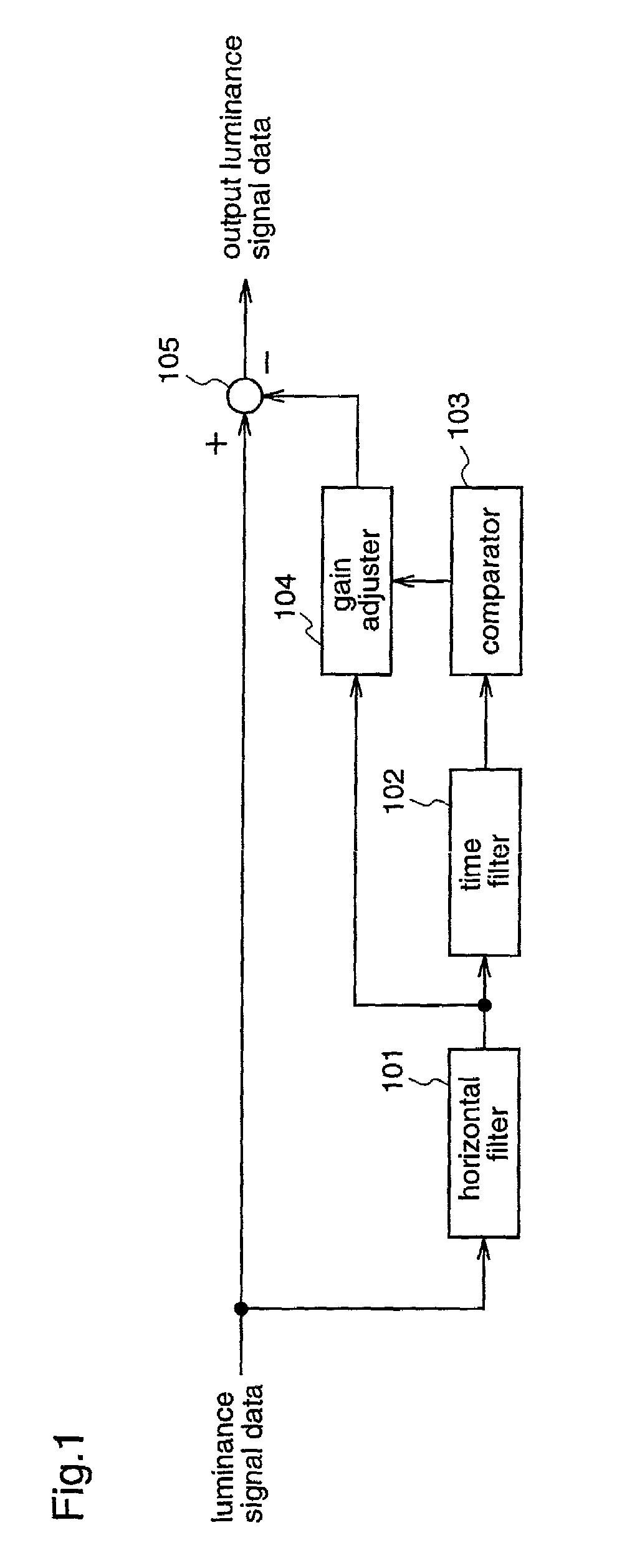
[0050]FIG. 1 is a block diagram illustrating a structure of a video signal processing apparatus according to a first embodiment of the present invention. In FIG. 1, reference numeral 101 denotes a horizontal filter, numeral 102 denotes a time filter, numeral 103 denotes a comparator, numeral 104 denotes a gain adjuster, arid numeral 105 denotes a subtracter.

[0051]The video signal processing apparatus according to the first embodiment eliminates dot crawls from a component video signal. Here, the operation of the video signal processing apparatus according to the first embodiment will be described.

[0052]Luminance signal data of the component video signal is inputted to the video signal processing apparatus of FIG. 1. The input luminance signal data is filtered by the horizontal filter 102. Here, the frequency characteristics of the horizontal filter 101 are those of a band-pass filter having the frequency of 3.58 MHz of a carrier signal in an NTSC signal as a pass-band....

embodiment 2

[Embodiment 2]

[0062]FIG. 4 is a block diagram illustrating a structure of a video signal processing apparatus according to the second embodiment of the present invention. In FIG. 4, numerals 401 to 403 denote a frame memory, respectively. Numeral 404 denotes a horizontal filter. Numeral 405 denotes a cross color detector. Numeral 406 denotes a gain adjuster. Numerals 407 to 410 denote a subtracter, respectively.

[0063]The video signal processing apparatus of the second embodiment eliminates cross color interferences from a component video signal.

[0064]In an NTSC signal, a color signal is multiplexed into a luminance signal. In this case, a signal that is obtained by modulating a color subcarrier (frequency of 3.58 MHz) with a color signal is multiplexed. The frequency of 3.58 MHz is 227.5 times as high as the horizontal scan frequency (15.75 kHz). Therefore, the color subcarriers of adjacent scan lines in the same field are shifted by a half cycle, which are shown in FIG. 18.

[0065]FI...

embodiment 3

[Embodiment 3]

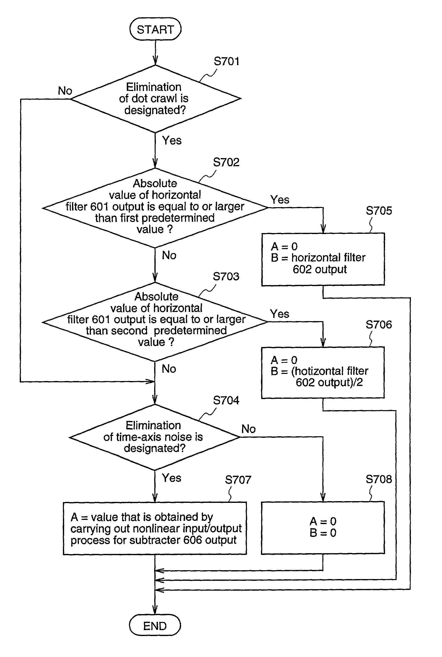
[0078]A video signal processing apparatus according to a third embodiment of the present invention simultaneously eliminates an arbitrary combination of noises among three noises of dot crawls, cross color interferences, and time-axis noises, from a component video signal. Here, the time-axis noises refer to noises of minute level occurring at random in the temporal direction.

[0079]Initially, a method for designating which combination of noises among the three noises is to be eliminated will be described with reference to FIG. 19. FIG. 19 is a block diagram illustrating a structure of a video signal processing apparatus comprising a video signal processing means 1001, an input accepting means 1002, and a display means 1003.

[0080]In the video signal processing apparatus of the third embodiment, the user designates which noises are to be eliminated among three noises of dot crawls, cross color interferences and time-axis noises. The display means 1003 makes a display for...


PUM


Abstract

A video signal processing method and apparatus eliminates dot crawls and cross color interferences from a component video signal that has been subjected to Y/C separation. Components at a horizontal frequency of 3.58 MHz and a temporal frequency of 15 Hz are extracted from luminance signal data using a horizontal filter and a time filter. When the absolute value of the component value is equal to or larger than a predetermined value, an output of the horizontal filter is subtracted from the luminance signal data by a subtracter, thereby eliminating dot crawls.

Description

FIELD OF THE INVENTION[0001]The present invention relates to a video signal processing method and apparatus for eliminating dot crawls or cross color interferences from a component video signal after being subjected to Y / C separation.BACKGROUND OF THE INVENTION[0002]When the Y / C separation is performed for a composite video signal, harmful influences such as dot crawls (which are also called “cross luminance interferences”) and cross color interferences occur. The Y / C separation is classified broadly in three types, and these three types of separation are referred to as one-dimensional Y / C separation, two-dimensional Y / C separation, and three-dimensional Y / C separation, respectively. Here, three-dimensional frequency characteristics of two-dimensional Y / C separation are shown in FIG. 17, as an example. FIG. 17 represents an NTSC signal in three-dimensional frequency space. In FIG. 17, a large rectangular parallelepiped 1001 in the center represents the band of the luminance signal, ...

Claims


Application Information

Patent Timeline
IPC IPC(8): H04N5/21H04N9/64H04N21/485
CPCH04N9/646H04N21/485
Inventor KONDO, SATOSHIITANI, TETSUYA
Owner PANASONIC CORP
Why Eureka
Try Eureka