Liquid-crystal display device and light pipe

a display device and liquid crystal technology, applied in the direction of waveguides, identification means, instruments, etc., can solve the problems of heavy device weight and complicated device structure, and achieve the effects of reducing contrast, good visual recognition, and excellent brightness

Inactive Publication Date: 2006-03-14
NITTO DENKO CORP
View PDF23 Cites 12 Cited by
  • Summary
  • Abstract
  • Description
  • Claims
  • Application Information

AI Technical Summary

Benefits of technology

[0007]An object of the present invention is to develop a liquid-crystal display device of good visual recognition which is excellent in brightness both in reflection and transmission modes, and in which both display inversion and lowering of contrast due to leakage of light do not occur.

Problems solved by technology

As a result, the structure of the device is complicated because of increase in the number of parts and arrangement and fixation of the reflection plate.
As a result, there is a disadvantage that the weight of the device becomes heavy because a thick support is required for preventing disorder of display from being caused by generation of wrinkles.

Method used


Image

  • Liquid-crystal display device and light pipe
  • Liquid-crystal display device and light pipe
  • Liquid-crystal display device and light pipe

Examples


example 1

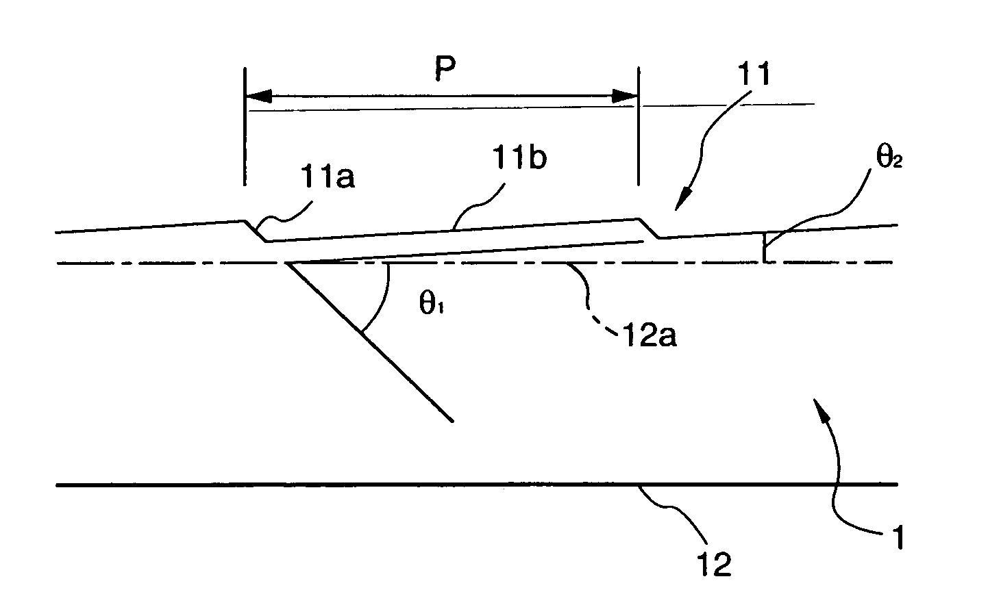
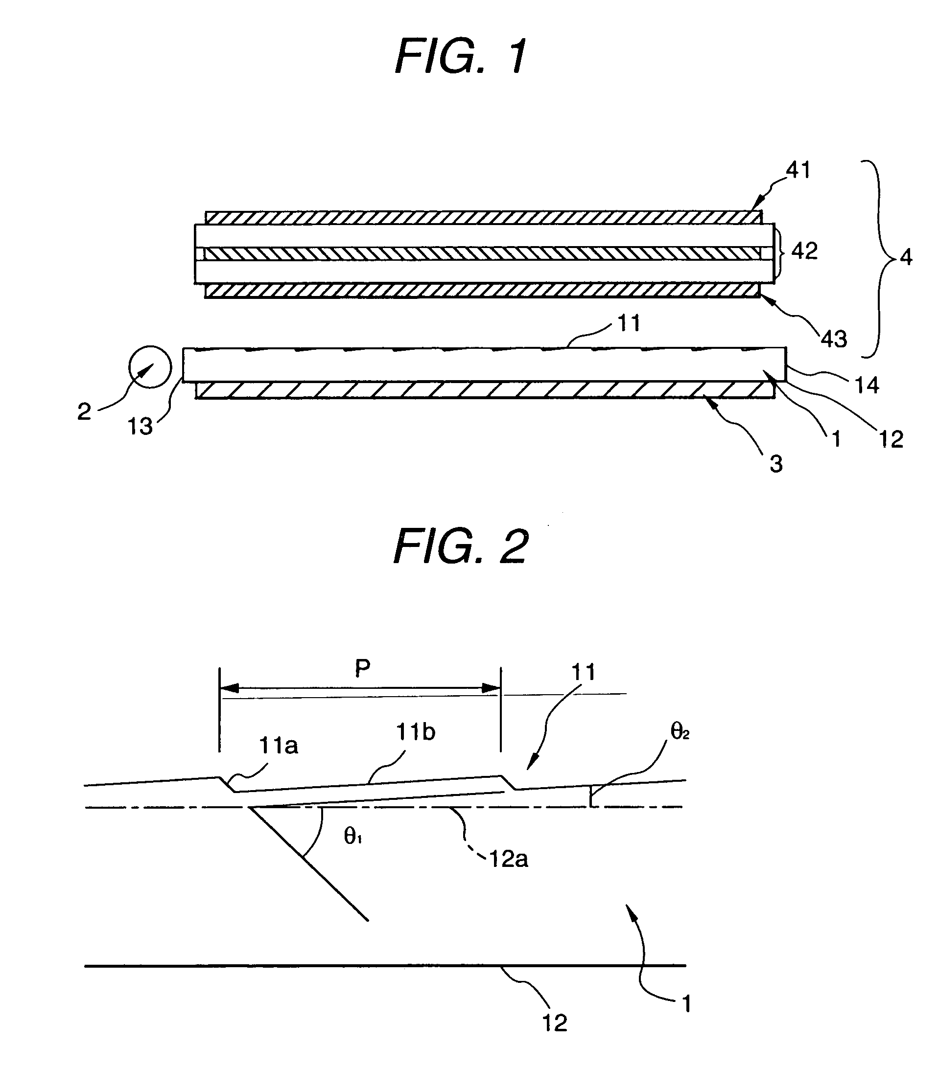
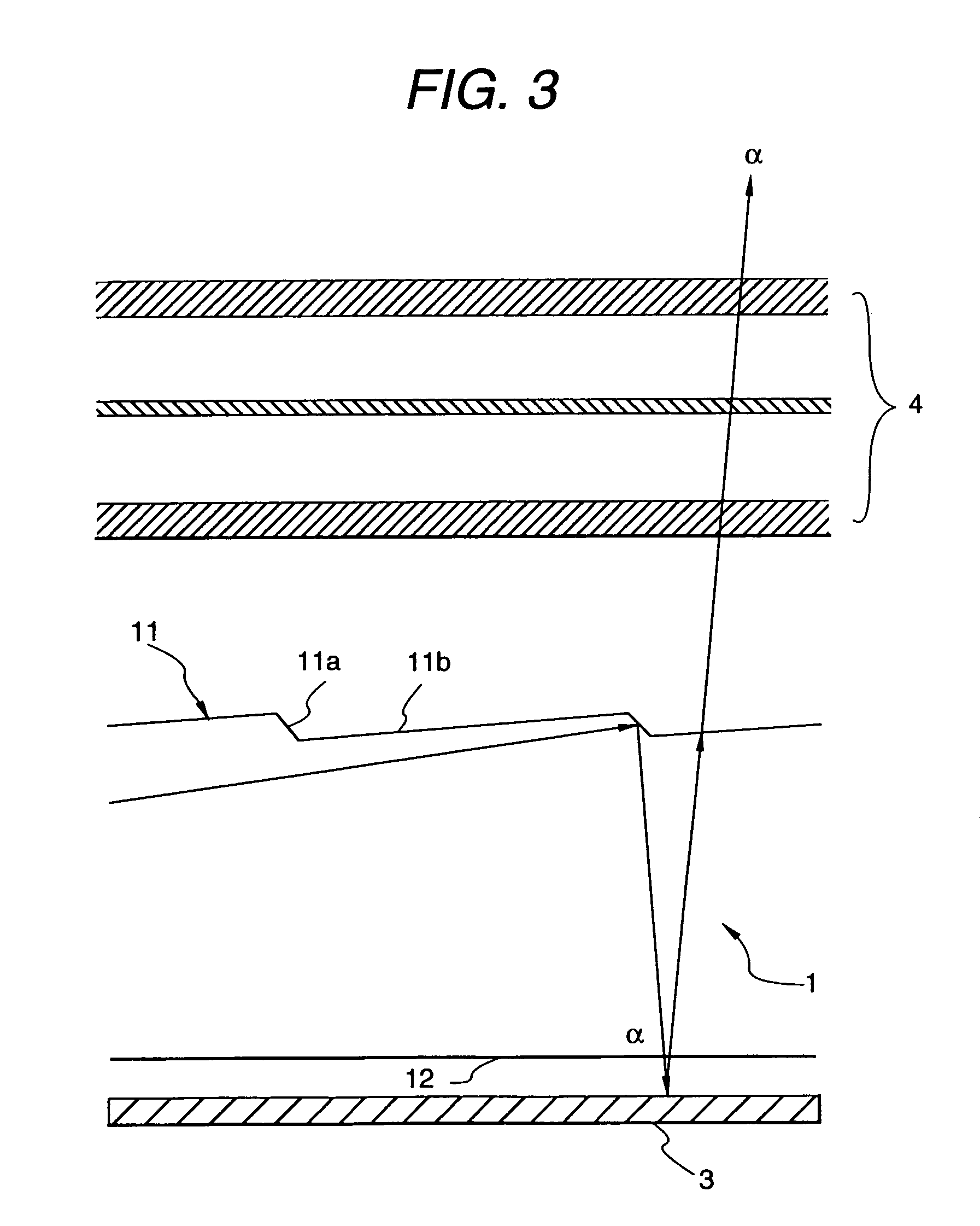
[0064]A surface of a polymethyl methacrylate plate processed into a predetermined shape in advance was cut by a diamond bit so that a light pipe having light output means at its upper surface was obtained. The light pipe was 40 mm wide and 25 mm deep. The light pipe was 1 mm thick at its incident side surface and 0.6 mm thick at its opposite end. Upper and lower surfaces of the light pipe were flat. The light pipe had prism-like irregularities at its upper surface. The prism-like irregularities were arranged at intervals of a pitch of 210 μm so as to be parallel with the incident side surface. Each of the prism-like irregularities had a short side surface inclined at an inclination angle changing in a range of from 42.5 to 43 degrees, and a long side surface inclined at an inclination angle changing in a range of from 1.8 to 3.5 degrees. The change of the inclination angle between adjacent long side surfaces was within 0.1 degrees. The protected width of the short side surface on th...

example 2

[0066]A liquid-crystal display device was obtained according to Example 1 except that the silver reflection plate was bonded by a tacky layer to the lower surface of the light pipe through the reflection surface of the silver reflection plate.

example 3

[0067]A liquid-crystal display device was obtained according to Example 1 except that a reflection sheet having a mirror silver reflection surface was used as a substitute for the silver reflection plate and was bonded to the lower surface of the light pipe through the reflection surface by a tacky layer containing silicone resin.


PUM

PropertyMeasurementUnit
inclination angleaaaaaaaaaa

Abstract

A liquid-crystal display device has a light pipe, a light source, a reflection layer, and a liquid-crystal shutter. The light pipe includes light output means formed on an upper surface of the light pipe. The light source is disposed near to an incident side surface of the light pipe so that light incident from the light source is output from a lower surface of the light pipe through the light output means. The reflection layer is disposed on the lower surface of the light pipe so that reflected light of the output light is transmitted through the upper surface of the light pipe. The liquid-crystal shutter is disposed above the upper surface of the light pipe, the liquid-crystal shutter including liquid-crystal cells and at least one polarizing plate.

Description

BACKGROUND OF THE INVENTION[0001]1. Field of the Invention[0002]The present invention relates to a liquid-crystal display device which is excellent in light utilizing efficiency and which provides a brilliant display easy to see, and a light pipe which can be used for forming the liquid-crystal display device.[0003]The present application is based on Japanese Patent Application No. Hei. 11-111756, which is incorporated herein by reference.[0004]2. Description of the Related Art[0005]There is investigation of a liquid-crystal display device which is used both in a reflection and a transmission mode so that the device can be visually recognized in use of the transmission type liquid-crystal display device in a dark place, or the like, by addition of an illuminator while the merit of a reflection type liquid-crystal display device of small power consumption is used widely. For example, there have been proposed a liquid-crystal display device using a semi-transmission type reflection pl...

Claims


Application Information

Patent Timeline
Patent Type & Authority Patents(United States)
IPC IPC(8): G02F1/1335G09F9/00F21V8/00G02B6/00G02F1/13G02F1/13357
CPCG02B6/0038Y10S385/901G02B6/0055G02B6/0028G02F1/133536G02F1/133615
Inventor UMEMOTO, SEIJI
Owner NITTO DENKO CORP
Why Eureka
Try Eureka