The results of these substantially manual techniques for
circuit extraction are often difficult to analyze.
Difficulties arise in tracing signals that travel between several schematics.
The signal renaming process creates two problems.
Firstly, it takes some time to locate each schematic associated with a particular signal such that the signal can be relabeled on each schematic where it appears.
Secondly, guaranteeing that the signal has been renamed on each schematic is difficult.
This can result in inconsistencies with signal names that can confuse the engineer attempting to analyze the circuitry.
However, such a cross-reference is very labor intensive to produce.
Once the schematics have been entered into a computer for
simulation and / or subsequent analysis, it becomes difficult to edit the schematics.
Editing a set of schematics in such a way can often cause errors in the net
list which require manual correction.
Unfortunately, the
circuit extraction method disclosed by Lam has the same restrictions as the manual method when in comes to locating signals and schematics, creating signal and schematic lists, and editing existing schematics.
In fact, the
automated method adds the burden of identifying logic gates and standard cells from a randomly organized net
list.
Obviously, this can take a very long period of time.
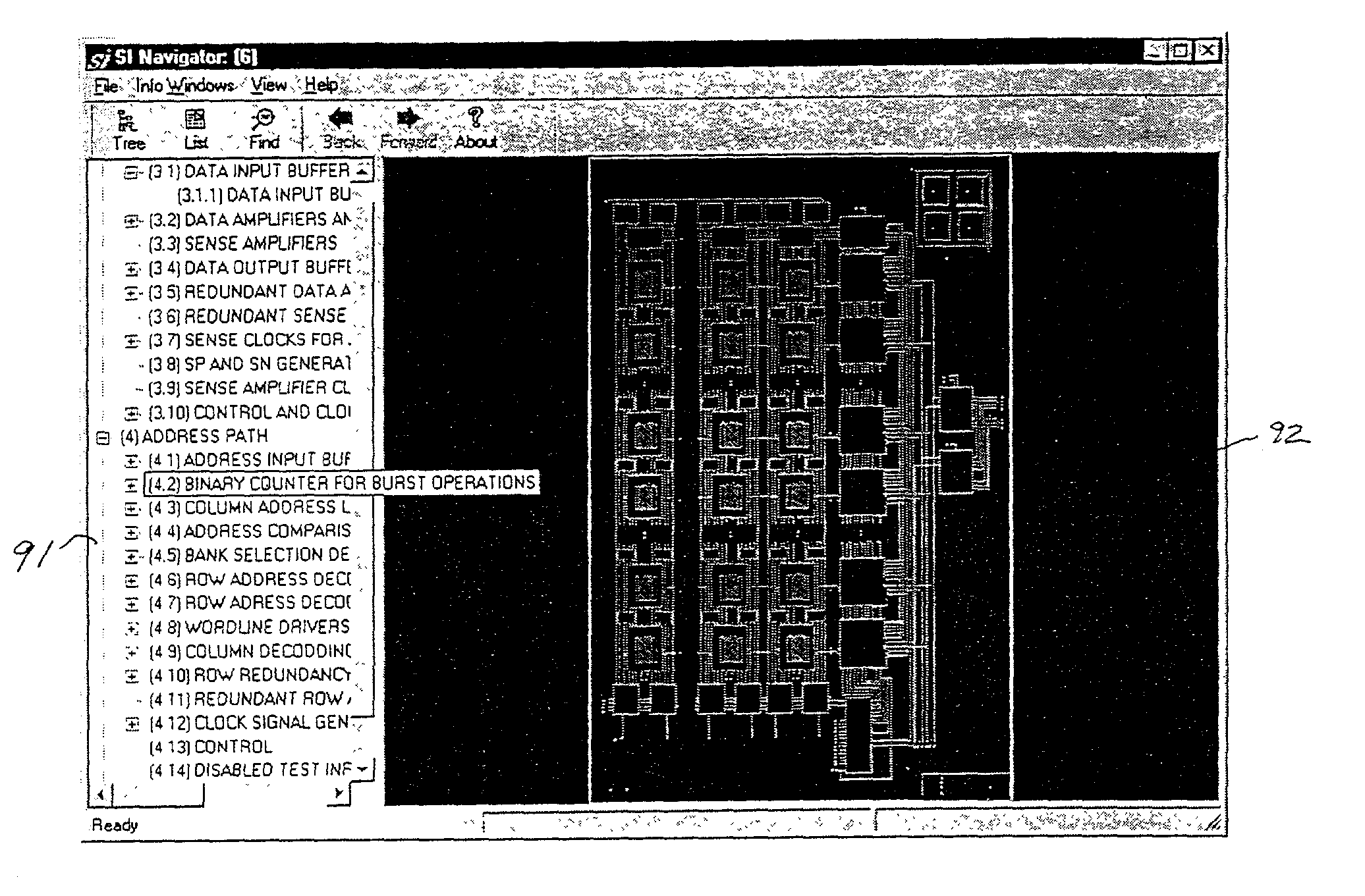
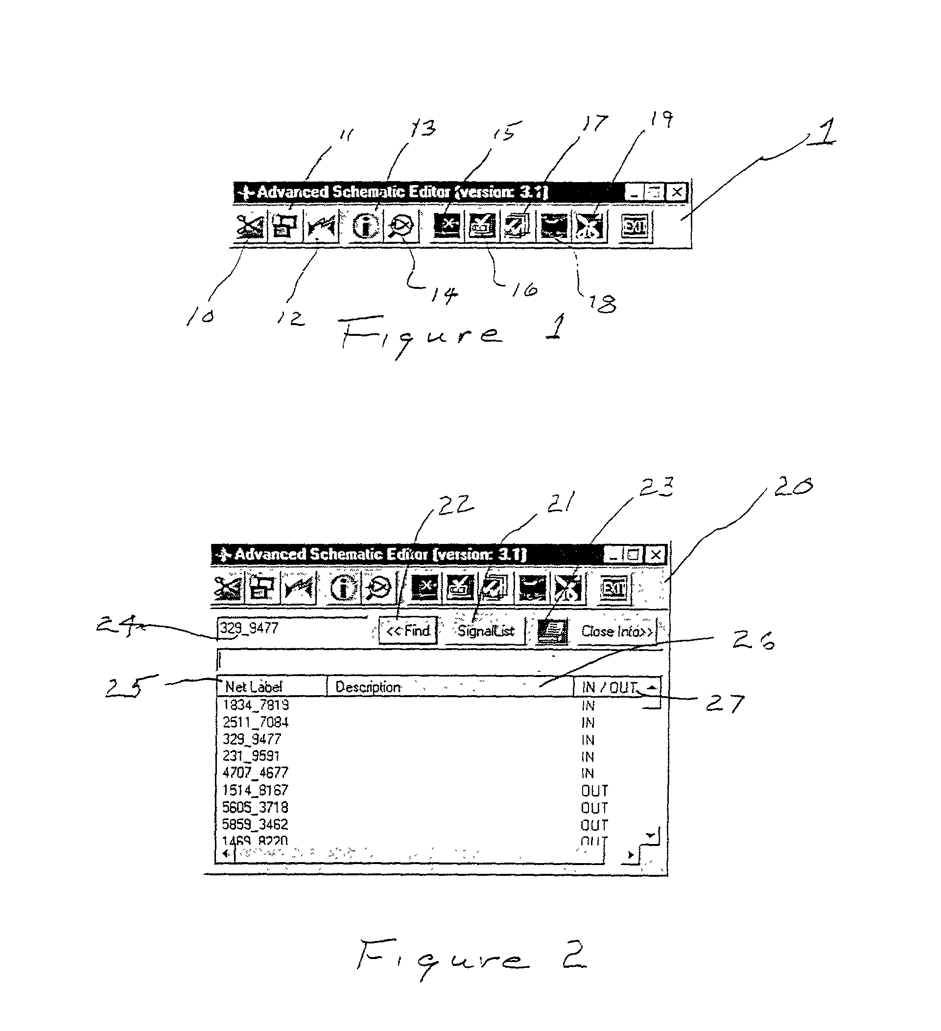
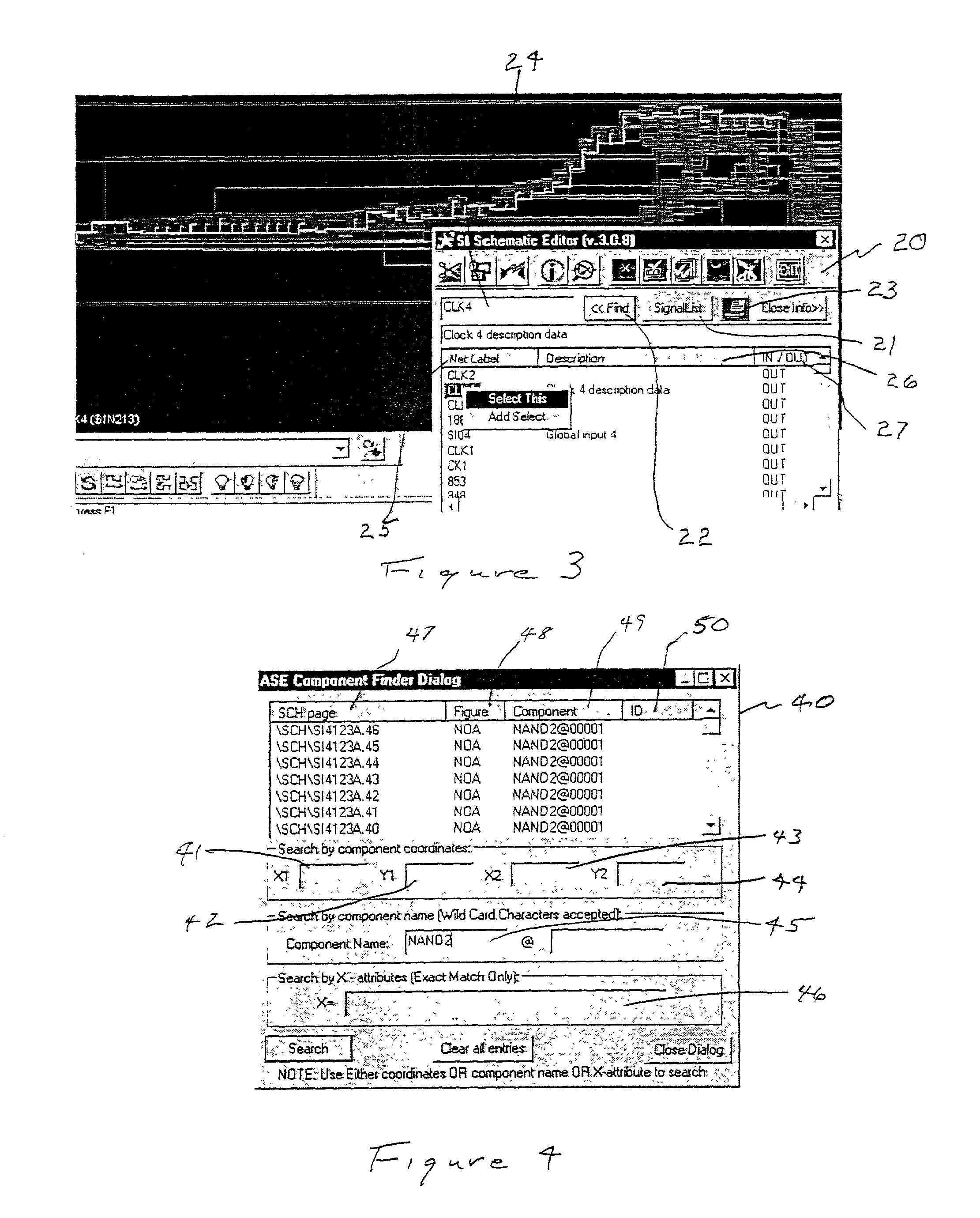
The following limitations of ViewDraw create difficulties and inconveniences for users in organizing schematics:1. The
cut procedure does not preserve interconnections at the boundary of cells.2. The paste procedure does not restore the wire or net interconnections that are lost for cells that are copied or cut elsewhere in the schematic.3. There is no way to automate the connection of a selected net or wire to the appropriate nets or wires on a schematic page.4. The signal and
cell search is limited to a currently opened schematic page only and doesn't consider sublevels of a flat type project.5. The search procedures do not provide very important information about objects such as: origin and destination of a signal,
exact location in the project, and user descriptions (annotations) of objects.6. There is no
cell / gate search based on important properties such as:
label, XY coordinates relative to the
layout location of objects, and
user defined attributes.7. There are no global editing capabilities such as: adding or removing particular wires, labels, and / or cells for local signals and IN / OUT symbols.8. There is no safe way of
cutting a net or wire and preserving both ends and their labels.
This limits customers in the ability to analyse the project data, to trace signals throughout the project schematic, and to follow the approach used in the design of the schematics.

