Color registration control system for a printing press

a control system and printing press technology, applied in office printing, printing, instruments, etc., can solve the problems of inability to transmit an image from the scanning unit, introduce color register errors between different printing units, and print plates may not be mounted or setup correctly on the plate cylinder, etc., to reduce the time it takes, easy to setup, and less sensitive to alignment

Inactive Publication Date: 2006-03-21
QUADTECH
View PDF79 Cites 41 Cited by
  • Summary
  • Abstract
  • Description
  • Claims
  • Application Information

AI Technical Summary

Benefits of technology

[0017]The present invention provides an improved color registration control system and method. The system includes a search method and system to search the paper substrate of a printing press laterally and circumferentially to decrease the time it takes to find the register mark pattern. The search method and system is able to provide a complete circumferential search for the register marks including searching and image processing every 30 milliseconds and utilizes small register marks on the order of 0.010″ for example.
[0018]The present invention also provides an improved scanning unit or camera assembly which is easy to setup and less sensitive to alignment. The camera assembly has a small footprint or profile and includes within a housing a scanner on a sensor board, a light source, an optics system, a main board including a microprocessor and hardware-based image processing implemented on FPGAs. The light source includes a single bulb type light source that provides dual light paths of uniform illumination using mirrors. The mirrors enable uniform illumination with a single bulb source and enable the camera assembly outer dimension to be narrow making it easier to mount on a printing press especially at the extremities of the web.
[0019]Synchronization between the light source, scanner and web-position encoder on the printing press is provided for. The method of synchronization eliminates the standard video timing, and instead creates image acquisition-on-demand timing.

Problems solved by technology

For instance, the printing plates may not be mounted or setup on the plate cylinder correctly.
Dynamics such as tension, stretch, ink coverage, and web weave can in turn introduce a color register error between different printing units.
It is normally difficult to transmit an image from the scanning unit to the processing unit without distortion, with the distance between the devices further contributing to the degradation of the high quality image processing desired.
Further, difficulties exist in transmitting such large amounts of data.
It can be difficult to setup and install the scanning unit properly on a printing press.
Synchronization can also be a challenge.
Precise synchronization can be difficult because it requires synchronization between a plurality of devices in the control system including proper lighting and the scanning unit.
Specifically, the synchronization becomes difficult because some area scanning units are not re-triggerable.
The problem in using these scanning units for any image recognition is that the scanning unit is typically running at a constant 30 Hz that is totally asynchronous to the speed of the printing press.
There is no guarantee that the scanning unit is in the right part of the printing cycle when the mark pattern is directly under the lens of the scanning unit.
Neither of these is desirable because it is difficult to identify if the dark image is caused by the synchronization problem or if it is an indication that the light source is too dark and hence requires adjustment.
These steps take time and result in the printed register marks moving a long distance in this period of time at high press speed.
However, the number of pulses required in the anticipation is dependent on the press speed, and this complicates the system design, its implementation and flexibility.
Deviation of marks from such relative dispositions is indicative of a registration error, i.e. misregistration.
The cost of maintaining two light sources is also high.
Some color registration control systems may either need to be told where to find the register marks, have limited searching capability, and / or require many plate revolutions to find the register marks.
Accordingly, make-ready time can be lengthy which results in waste of material and time.

Method used


Image

  • Color registration control system for a printing press
  • Color registration control system for a printing press
  • Color registration control system for a printing press

Examples


Embodiment Construction

[0035]In conjunction with the description of the preferred embodiment, a web offset printing press will be described. It should be noted, however, that the invention can be utilized on printing presses other than web offset presses.

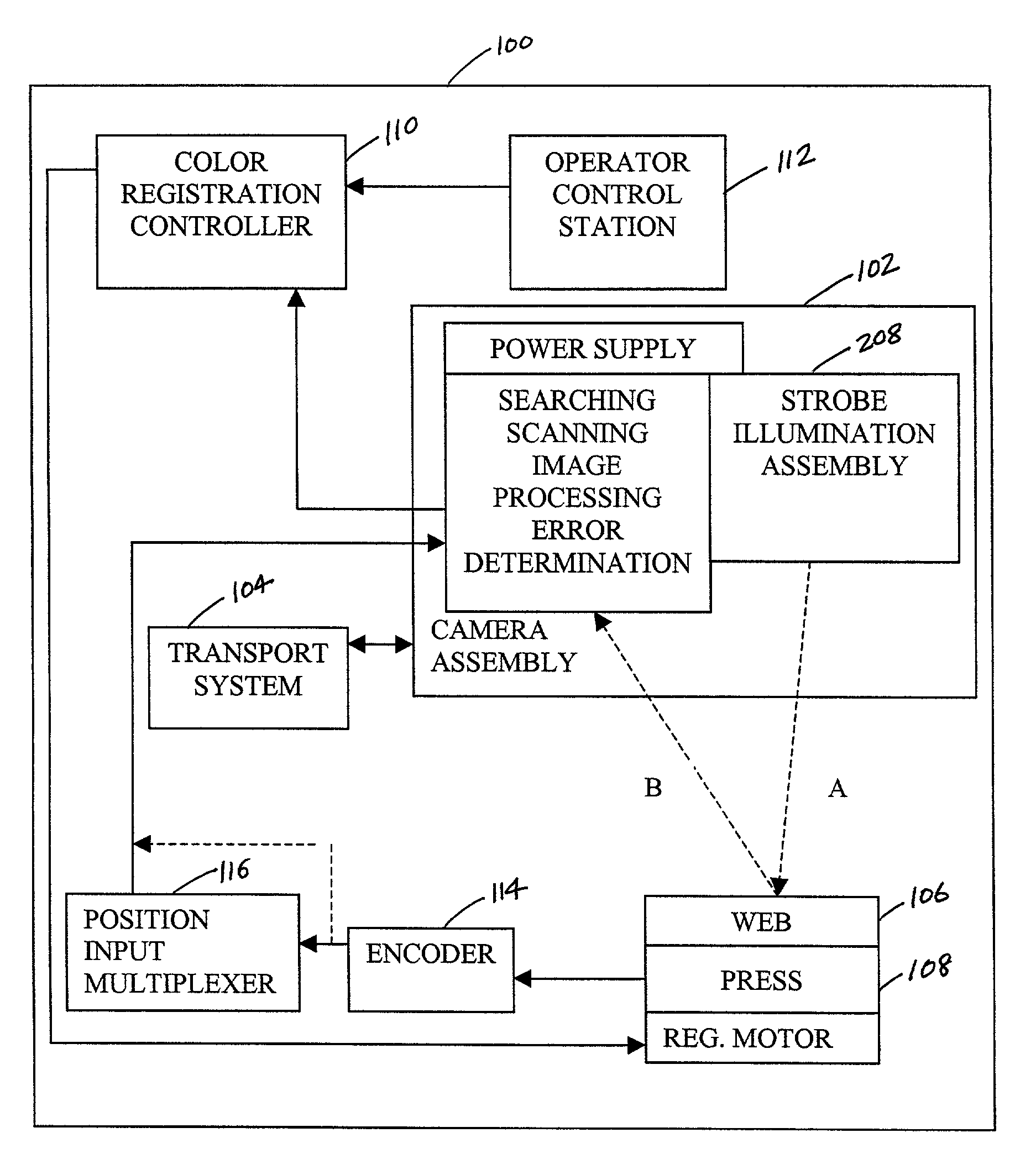
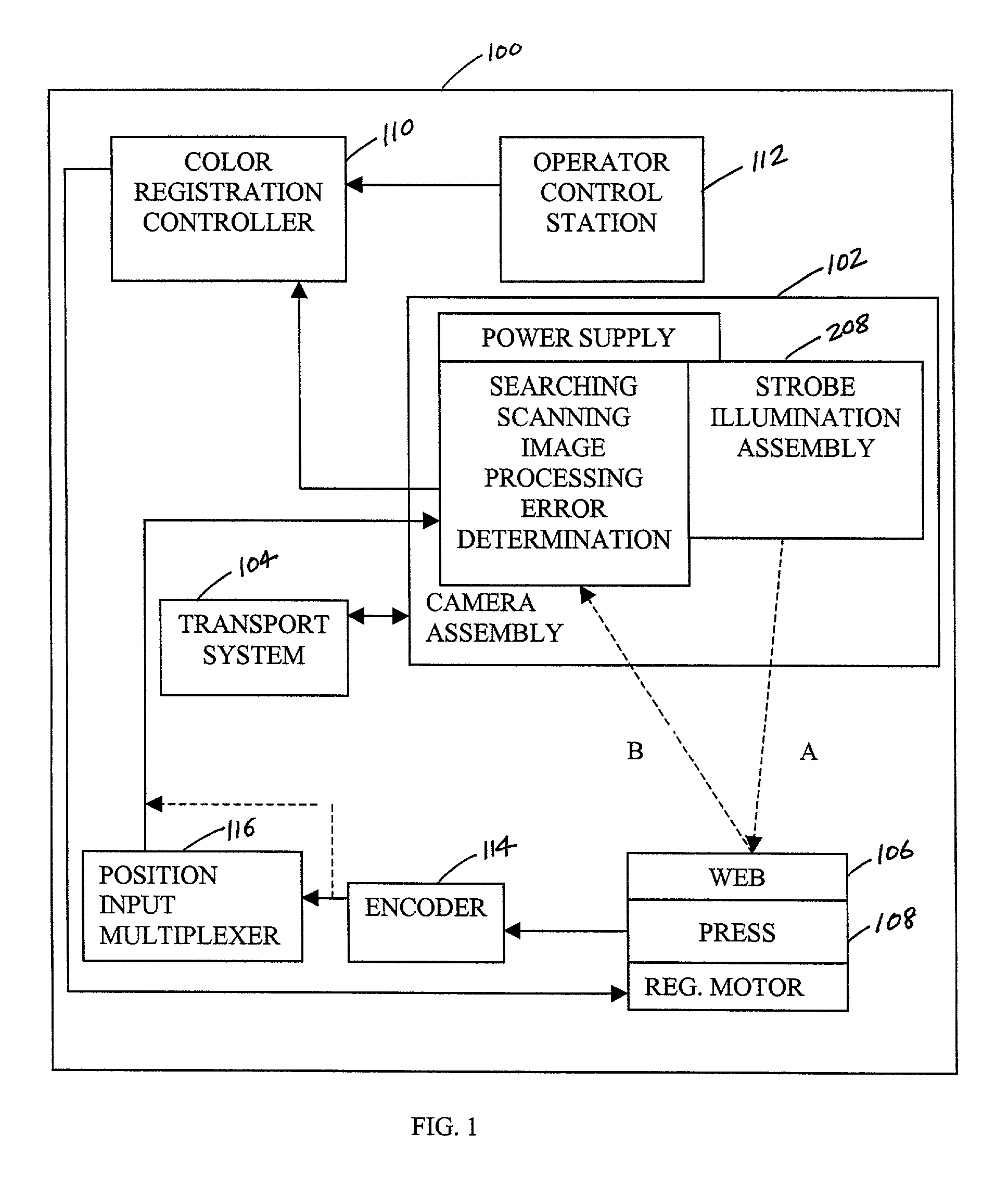
[0036]Referring to FIG. 1, a color registration control system 100 is shown and includes a scanning unit or camera assembly 102 and an associated transport system 104. The transport system 104 can be of a manual or automated design. Preferably, an automated design is used such as is known in the art. Generally, an automated transport system can include a linear actuator and a motor with a motor controller. The actuator consists of a bar, carriage, coupling mechanism, transport mechanism (e.g. screw or belt), and position encoder. Optionally, the transport system 104 may also include limit switches, jog buttons (to allow the operator to move the carriage), and indicators such as the direction it is moving and whether or not the camera assembly 102 is track...


PUM


Abstract

A color registration control system for a printing press including an area scanner for acquiring an image of a paper substrate and an image processing system adapted to receive the image and process the image to determine any color register error.

Description

FIELD OF THE INVENTION[0001]The present invention relates to a control system for a printing press, more particularly to a camera assembly for acquiring images of the paper substrate moving on the printing press, and more particularly to color registration control on a printing press.BACKGROUND OF THE INVENTION[0002]In web offset printing presses, a substrate such as a web of paper is sequentially driven through a series of print cylinders, each using ink of a different color, which cooperate to imprint a multicolor image on the web. To provide an accurate and clear multicolor image, the rotational and lateral position of each print cylinder must be precisely aligned, i.e., proper color registration of the respective colors must be maintained.[0003]Color registration control systems for printing presses are known in the art. An example of a closed-loop color registration control system is the commercially available RGS V From QTI of Sussex, Wis. The RGS V system provides a closed-lo...

Claims


Application Information

Patent Timeline
Patent Type & Authority Patents(United States)
IPC IPC(8): B41F5/16B41M1/14G03B27/32B41F33/14B41F13/02B41F33/00
CPCB41F13/025B41F33/0081B41F33/0036B41P2233/52
Inventor HANSEN, MARK R.RANTALA, GLEN W.MOERSFELDER, BRADLY
Owner QUADTECH
Why Eureka
Try Eureka