[0003]The pneumatic tire is the best known solution for compliance, comfort,
mass, and
rolling resistance; however, the pneumatic tire has disadvantages in complexity, the need for maintenance, and susceptibility to damage. A device that improves on pneumatic tire performance could, for example, provide more compliance, better control of stiffness, lower maintenance requirements, and resistance to damage.
[0014]The compliant band may be formed of an elastomeric material, such as natural or
synthetic rubber,
polyurethane, foamed rubber and foamed
polyurethane, segmented copolyesters and block co-polymers of nylon. Preferably, the material has an
elastic modulus of about 9 MPa to about 60 MPa. The band may be unreinforced, or may include a reinforcing ply to increase the band's circumferential inextensibility.
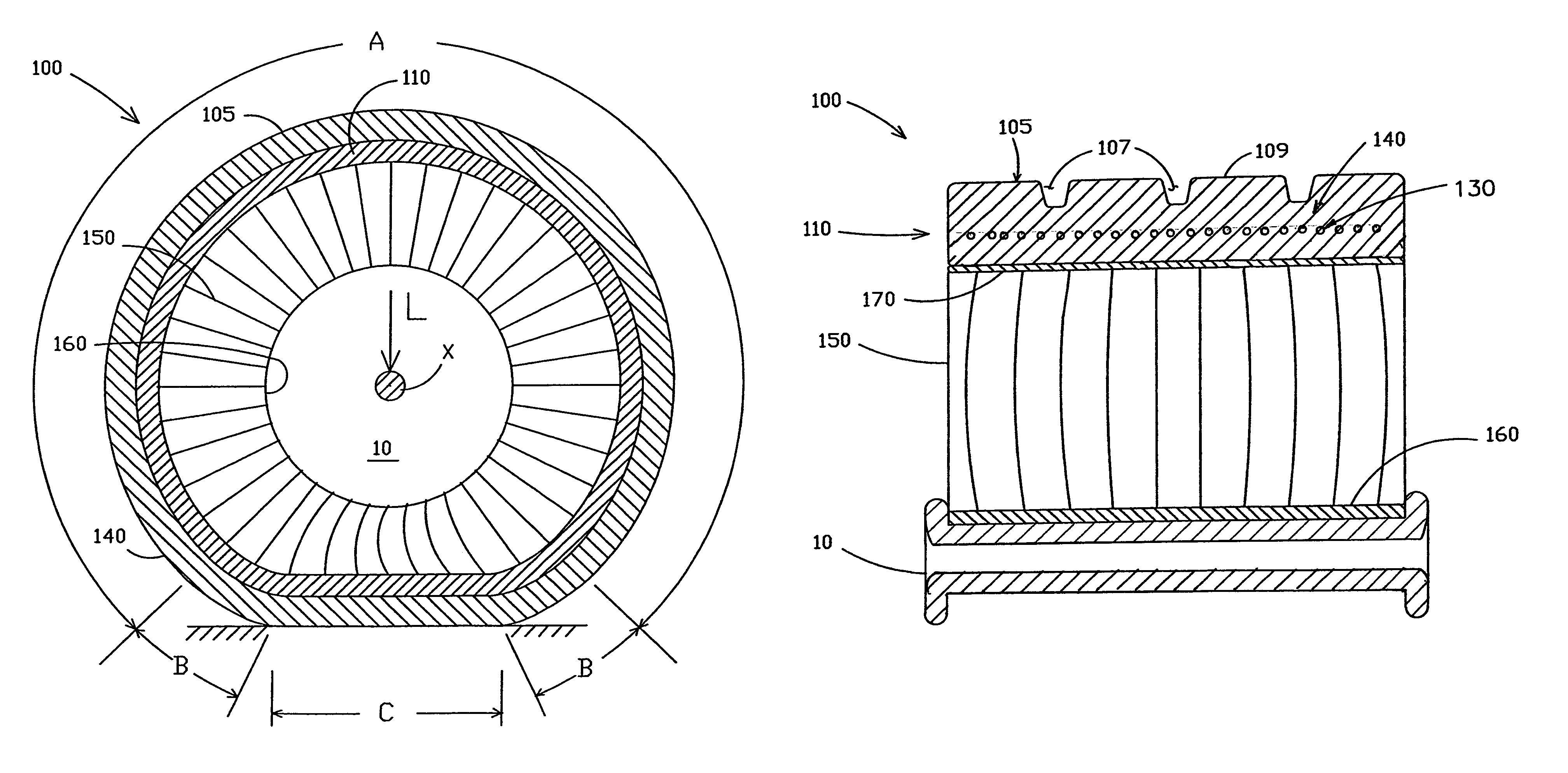
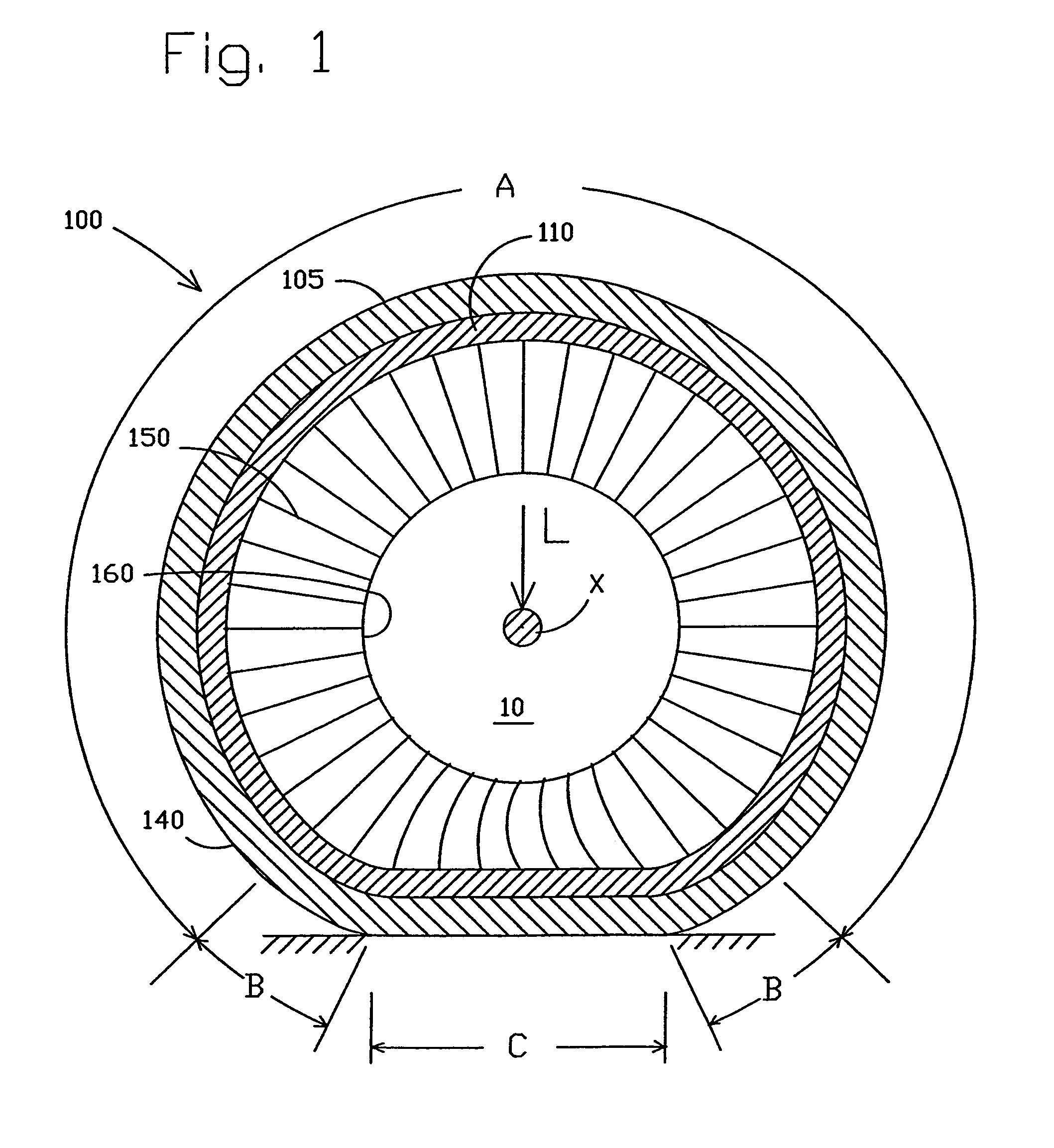
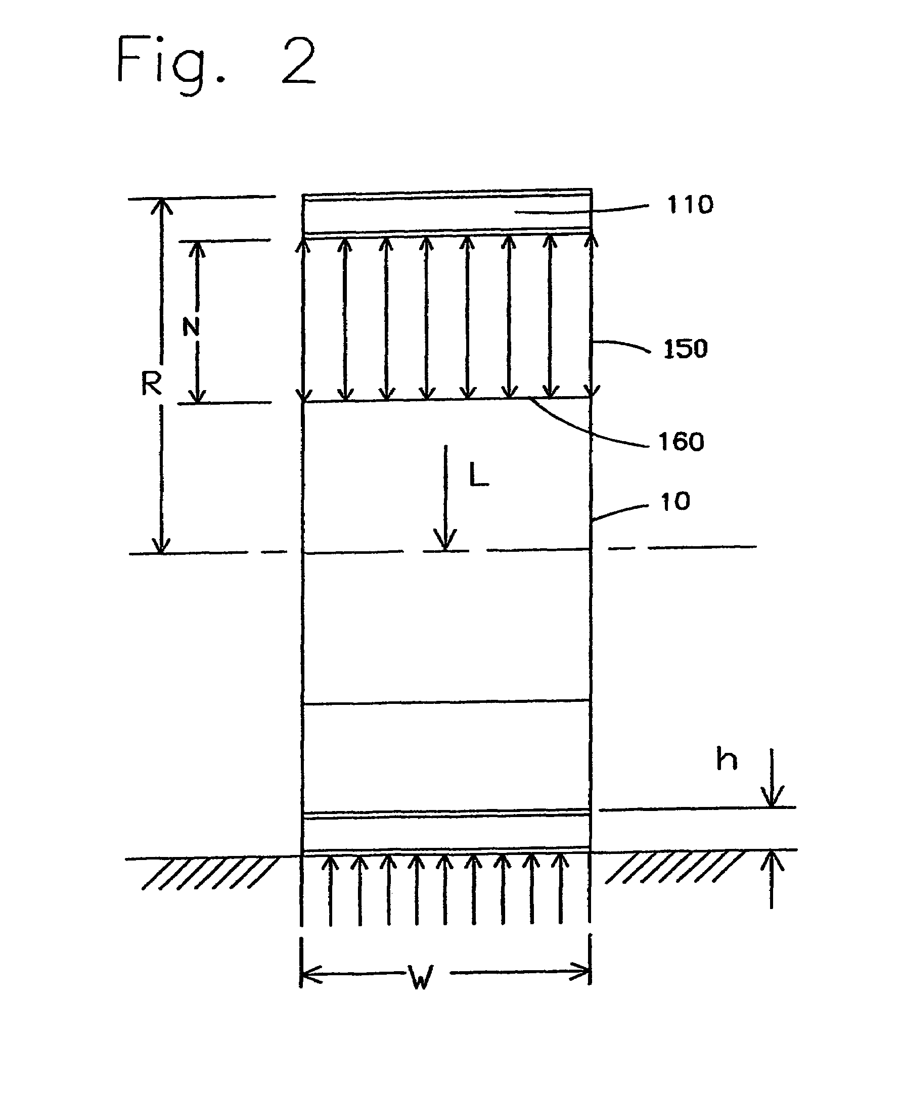
[0016]Preferably, the web spokes have a high
effective stiffness in tension and a low effective stiffness in compression. The low stiffness in compression allows the web spokes attached to the ground-contacting portion of the compliant band to accommodate deformation of the ground-contacting portion of the compliant band without transmitting significant
vertical load. The web spokes are relatively thin compared to their length, and typically, will bend in compression. The lack of
compressive load support by the web spokes in the
contact region allows the band to more easily form the
contact patch and to more easily bend to absorb obstacles. In addition, because there is no direct connection from the ground to the hub, i.e., road shock must travel around the compliant band and through the tensioned web spokes, the compliant wheel has improved comfort and shock absorption compared to pneumatic tires.
[0017]The web spokes also transmit the forces required for accelerating, stopping, and cornering. The arrangement and orientation of the web spokes can be selected to obtain the desired function. For example, in applications where relatively low circumferential stiffness is desired, the web spokes can be arranged radially and in parallel with the compliant wheel axis of rotation. To increase stiffness in the circumferential direction, web spokes perpendicular to the axis of rotation can be added, alternating with the axis-aligned web spokes. Another alternative is to arrange the web spokes oblique to the compliant wheel axis to provide stiffness in both the circumferential and axial directions. Another alternative is to orient the web spokes to be in an alternating oblique arrangement, that is, in a zig-zag pattern when viewed on the equatorial plane. Of course, other similar arrangements could be used to tailor the circumferential stiffness of the wheel.
[0018]To facilitate the bending of the web spokes of the ground contacting portion of the
tread, the spokes can be curved. Alternatively, the web spokes can be shaped during molding to have a predisposition to bend in a particular direction. Another alternative is to provide a connection between the hub and web spokes or between the ring and web spokes that acts in tension but allows relative movement of the web
spoke in compression.
[0019]According to a preferred embodiment of the invention, a compliant wheel comprises a hub, a compliant, load supporting band disposed radially outward and concentrically with the hub, and a plurality of web spokes extending between the hub and the compliant band, wherein the compliant band comprises a reinforcing membrane or ply embedded in the band. Preferably, the reinforcing ply comprises cords aligned in the circumferential direction embedded in an elastomeric layer. According to this embodiment, the reinforcing ply acts to constrain the circumferential length of the band under load forces for better application of tension to the web spokes, which increases the
load carrying capability.

