Drill bit having an improved seal and lubrication method using same

a technology of lubrication method and drill bit, which is applied in the field of drill bits, can solve the problems of rig operator's decision, difficulty in determining when to replace drill bits, and difficulty in determining the operating condition, performance and remaining useful life of drill bits, and achieves improved sealing, low coefficient of friction, and high resistance to heat and abrasion.

Inactive Publication Date: 2006-03-21
HALLIBURTON ENERGY SERVICES INC
View PDF59 Cites 117 Cited by
  • Summary
  • Abstract
  • Description
  • Claims
  • Application Information

AI Technical Summary

Benefits of technology

[0012]The present invention disclosed herein comprises a drill bit having an improved seal that can maintain the lubricant within the drill bit and prevent the flow of drilling fluid into the bearing. The seal of the present invention has a high resistance to heat and abrasion, has a low coefficient of friction and does not significantly deform under load. In addition, the seal of the present invention is resistant to chemical interaction with hydrocarbons fluids encountered within the wellbore and has a long useful life.
[0014]The drill bit body includes a pressure-compensated reservoir in fluid communication with the bearing surfaces of each journal pin and rotary cutter combination. The pressure-compensated reservoir has a lubricant therein that lubricates the bearings between the bearing surfaces. A diaphragm is positioned within the pressure-compensated reservoir. The diaphragm transmits pressure from the region surrounding the drill bit to the lubricant within the pressure-compensated reservoir. A seal element is positioned between each journal pin and rotary cutter. The seal elements retain the lubricant in the bearing surfaces and prevent fluids from exterior of the drill bit from entering the bearing surfaces. The seal elements may be any suitable seals including o-ring seals, d-seals, t-seals, v-seals, flat seals, lip seals and the like.

Problems solved by technology

Unfortunately, once a drill bit is positioned in a wellbore, gathering reliable information regarding the operating condition, performance and remaining useful life of the drill bit becomes difficult.
The rig operator's decision, however, as to when to replace a drill bit is often not the most cost effective because of the many factors affecting drilling performance beyond the condition and performance of the bit itself.
In addition, it is not uncommon for a drill bit to fail during the drilling operation.
Bit failure may occur due to a variety of factors.
For example, a bit may fail due to an improper application of the bit, such as by excessive weight on the drill bit from the drilling string, excessive rotational speed, using the wrong type of bit for substrate being drilled and the like.
Regardless of the cause, the two most common types of bit failures are breakage of the cutting elements and bearing failure.
This breakage does not normally stop the drilling action but it does significantly reduce the rate of drilling penetration.
In the second mode of failure, once a bearing assembly has failed, continued use of the bit may result in the roller cutter separating from the bearing journal and remaining in the wellbore when the drill string is retrieved to the surface.
The lost roller cutter must then be retrieved from the wellbore in a time-consuming and expensive fishing operation in which a special retrieval tool is tripped in and out of the wellbore to retrieve the broken roller cutter.
In sealed bearing roller cutter bits, bearing failure is often the result of a seal failure that allows lubricant to flow out of the drill bit and drilling fluid, which contains abrasive particles, to flow into the bearing.
Although less common, diaphragm failure has the same result as seal failure.
In any event, bearing failure is almost always preceded by, or at least accompanied by, a loss of lubricant.

Method used


Image

  • Drill bit having an improved seal and lubrication method using same
  • Drill bit having an improved seal and lubrication method using same
  • Drill bit having an improved seal and lubrication method using same

Examples


Embodiment Construction

[0028]While the making and using of various embodiments of the present invention are discussed in detail below, it should be appreciated that the present invention provides many applicable inventive concepts which can be embodied in a wide variety of specific contexts. The specific embodiments discussed herein are merely illustrative of specific ways to make and use the invention, and do not delimit the scope of the present invention.

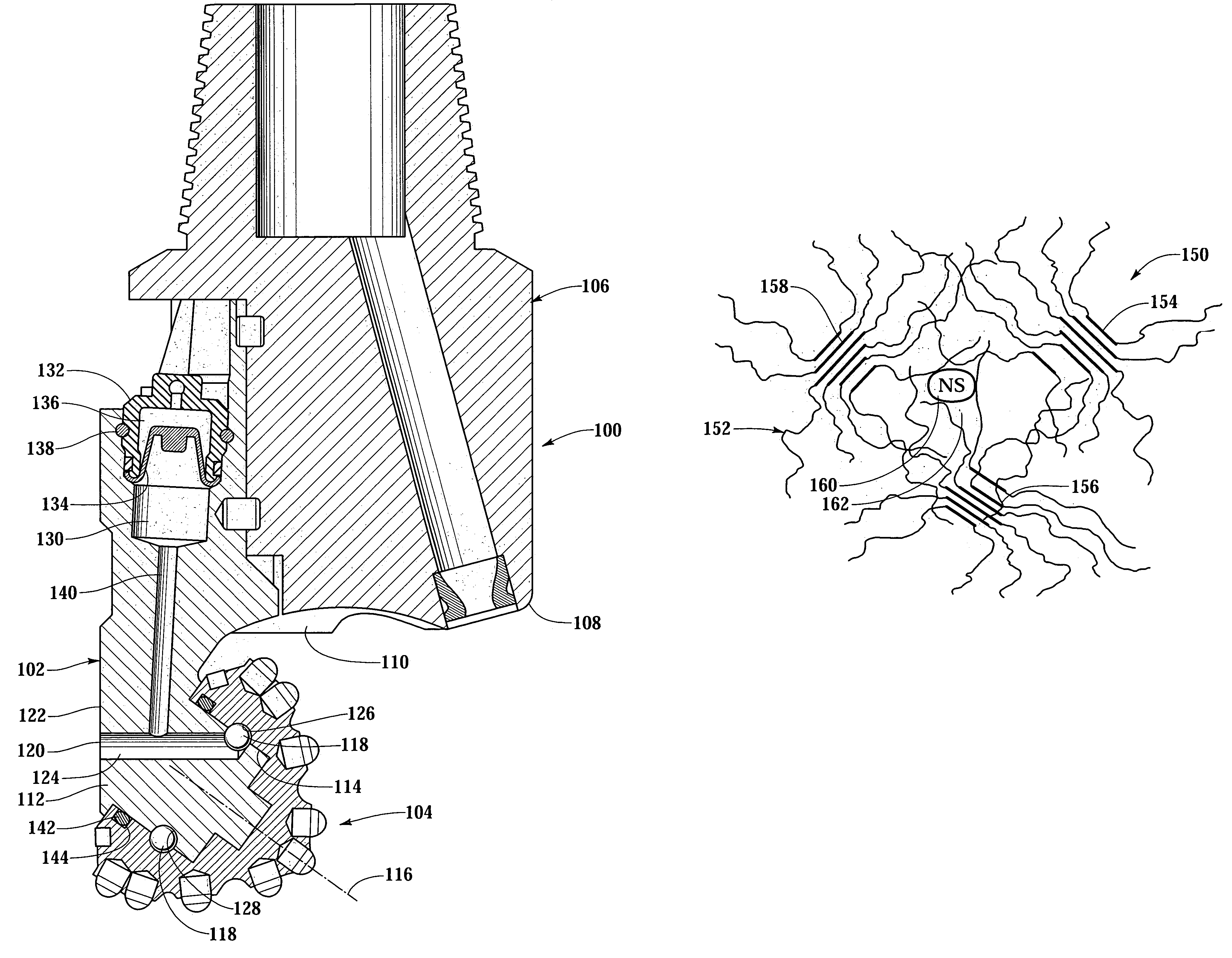
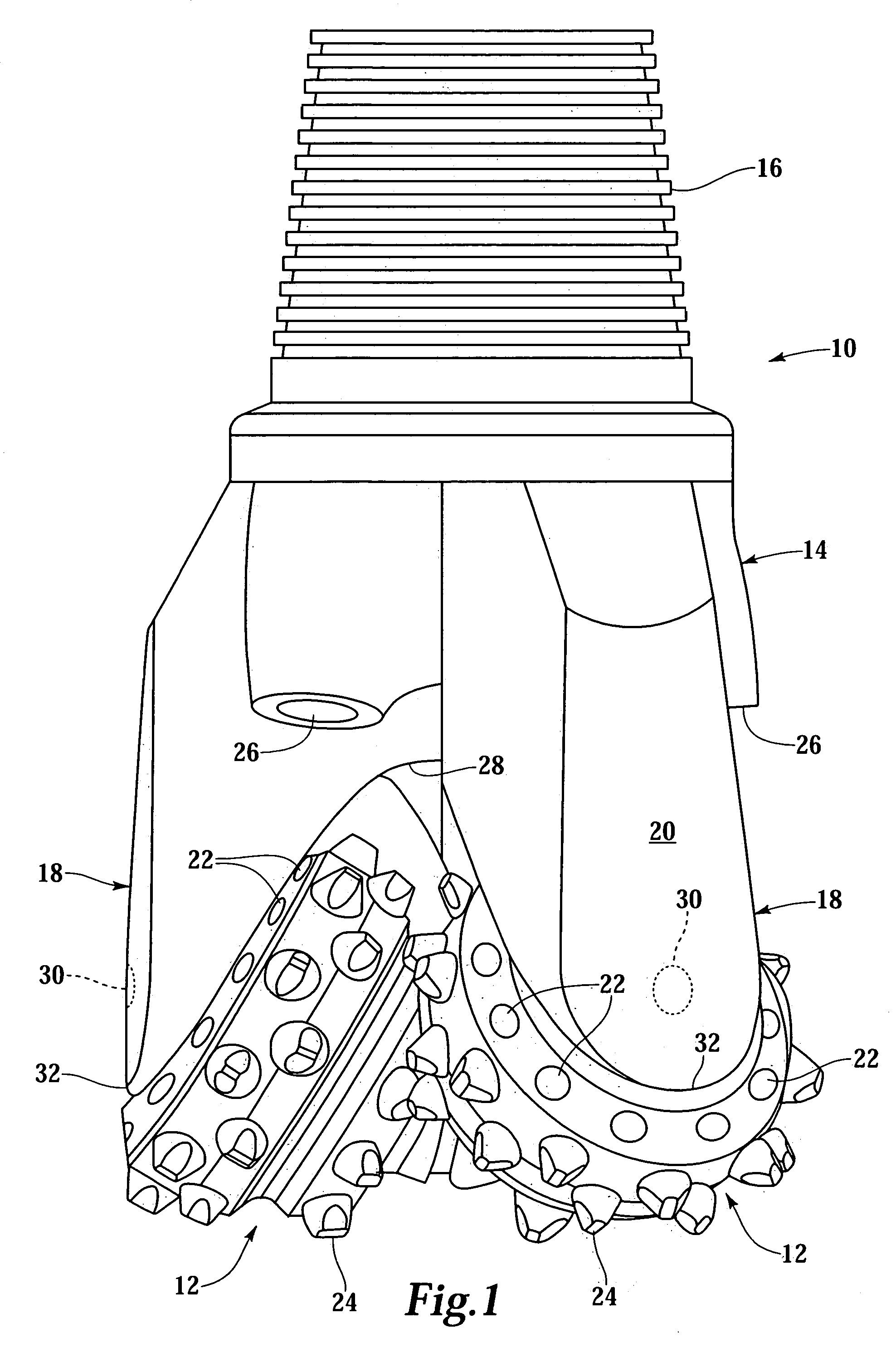
[0029]Referring initially to FIG. 1, therein is depicted a rotary cone drill bit of the type used in drilling a wellbore that traverses a subterranean hydrocarbon bearing formation that is schematically illustrated and generally designated 10. Rotary cone drill bit 10 includes a plurality of cone-shaped rotary cutter assemblies 12 that are rolled around the bottom of a wellbore by the rotation of a drill string attached to drill bit 10. Each rotary cutter assemblies 12 is rotatably mounted on a respective journal or spindle with a bearing system, sealin...


PUM


Abstract

A drill bit (100) for drilling a wellbore that traverses subterranean formations includes a drill bit body (106) having a plurality of journal pins (112), each having a bearing surface (128), and a rotary cutter (104) rotatably mounted on each journal pin (112), each rotary cutter (104) including a bearing surface (126). A pressure-compensated reservoir (130) is in fluid communication with the bearing surfaces (126, 128) and has a lubricant therein. A seal element (144) is positioned between each journal pin (112) and rotary cutter (104) and retains the lubricant in the bearing surfaces (126, 128). The seal element (144) is formed from a nanocomposite material including a polymer host material and a plurality of nanostructures.

Description

TECHNICAL FIELD OF THE INVENTION[0001]This invention relates, in general, to drill bits used for drilling a well that traverses a subterranean hydrocarbon bearing formation and, in particular, to an improved seal for a rotary drill bit than maintains lubricant within the drill bit and prevents the flow of drilling fluid into the bearing of the drill bit.BACKGROUND OF THE INVENTION[0002]Without limiting the scope of the present invention, its background will be described with reference to using rotary drill bits to drill a well that traverses a subterranean hydrocarbon bearing formation, as an example.[0003]Rotary drill bits are commonly used to drill wells in the oil and gas well drilling industry as these rotary drill bit offers a satisfactory rate of penetration with a significant operational life in drilling most commonly encountered formations. Typically, a rotary drill bit includes a bit body having a threaded pin at its upper end adapted to be detachably secured to a drill str...

Claims


Application Information

Patent Timeline
Patent Type & Authority Patents(United States)
IPC IPC(8): E21B10/22E21B10/25
CPCE21B10/25
Inventor RAY, THOMAS WAYNEBOYCE, JAMES EDWARD
Owner HALLIBURTON ENERGY SERVICES INC
Why Eureka
Try Eureka