Endurable decoration light string

a technology of light strings and decorations, applied in the direction of lighting support devices, coupling device connections, lighting and heating apparatus, etc., can solve the problems of incompleteness and unfavorable beauty, and achieve the effect of increasing the life of the decoration

Active Publication Date: 2006-03-21
CHEN JOHNNY
View PDF16 Cites 43 Cited by
  • Summary
  • Abstract
  • Description
  • Claims
  • Application Information

AI Technical Summary

Benefits of technology

[0005]The purpose of the present invention is to provide an endurable decoration light string, and said light string is fixed on the predetermined fixed position of both the head and the tail ends and the central parts. The appropriate equipment can be installed to resist the draw force so as to increase the life span of the decoration light string.
[0006]A further purpose of present invention is to provide an endurable decoration light string by means of a non-electrical connector so that the draw force of the decoration light string will be firstly supported by non-electrical connector to avoid the damage on the decoration light string whereby to increase life time on the decoration light string. Further, the strength of the draw force of the non-electrical connector is greater than that of single or multiple electrical conductors and the rate of extension is small than that of electrical conductor.
[0009]Further, in the present invention of endurable decoration light string, another characteristic is that when the multiple electrical conductors separate out to connect with the luminaries, the multiple electrical conductors on one side of long trunk can be a curve. Therefore, after tying a knot firmly with non-electrical connector, a buffering function is obtained. The electrical conductor will not be affected if the draw force is formed and the non-electrical connector will take the force instead of the electrical conductors.

Problems solved by technology

Even through this will not affect the whole decoration light string to start, however, the vision result will be affected more or less so that it is unfortunately beautiful and yet incomplete.

Method used


Image

  • Endurable decoration light string
  • Endurable decoration light string
  • Endurable decoration light string

Examples


Embodiment Construction

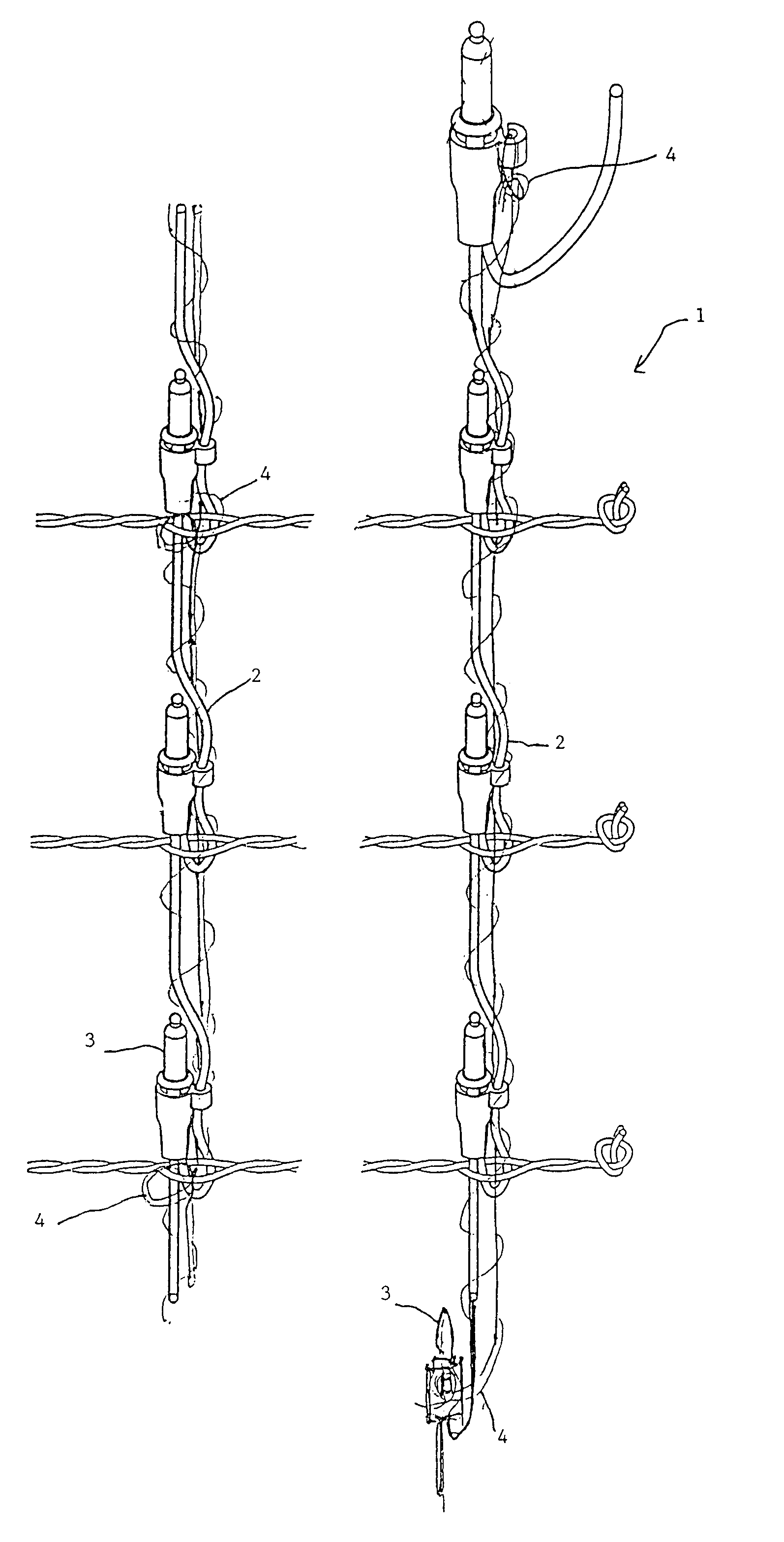
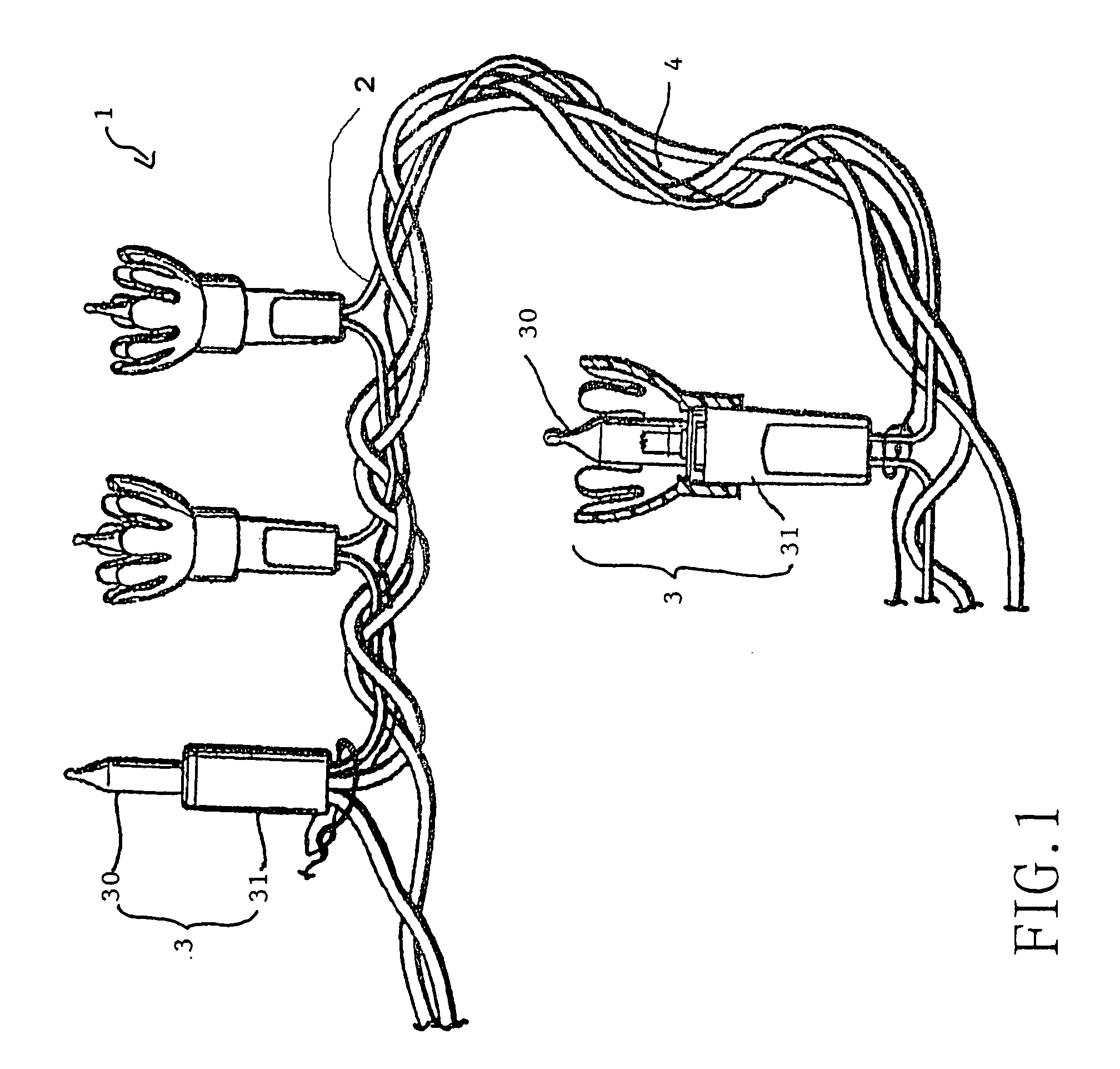
[0015]Now referring to FIG. 1, an endurable decoration light string 1 of the present invention includes: electrical conductor 2, luminary 3 and non-electrical connector 4, in which, the electrical conductor 2 is of a predetermined length. In this drawing, a small section is illustrated for description purpose. Each of luminaries 3 connected on electrical conductor 2 is composed of lamp bulb 30 and lamp holder 31. Further, along with electrical conductor 2, the non-electrical connector 4 is parallel and winding with the electrical conductor 2, also fixing a knot on the long trunk of the electrical conductor 2. Thus, the strength of draw force of the decoration light string 1 can be enhanced.

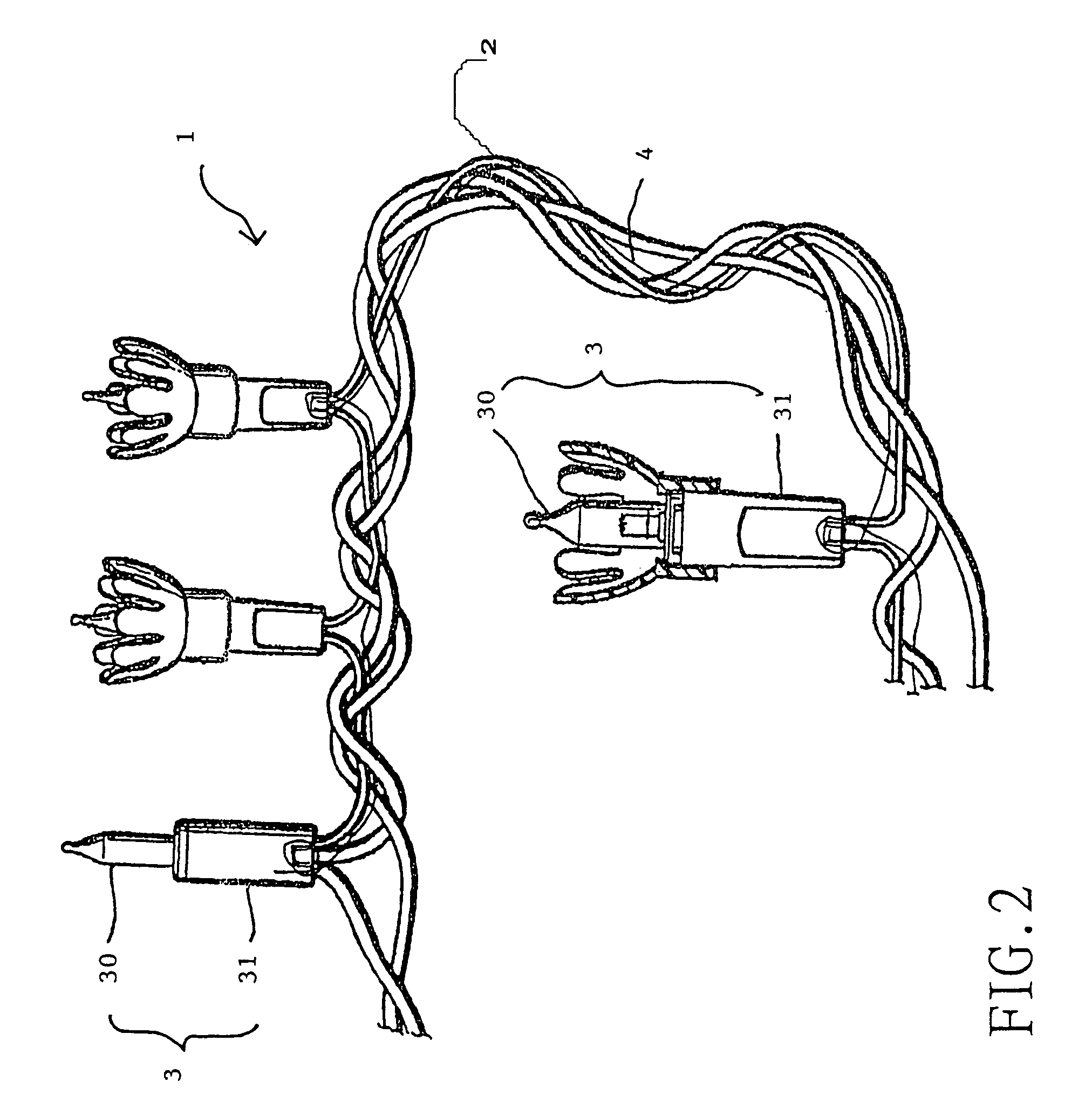
[0016]Similarly, FIG. 2 (also showing a small section of the decoration light string 1) is showing that one non-electrical connector 4 is used in parallel winding, and make a knot on luminary 3 so that the strength of draw force of decoration light string 1 can be enhanced.

[0017]Also, referring to...


PUM


Abstract

The present invention relates to an endurable decoration light string of light strings and one or more non-electrical connector. The light string includes mutually connective luminaries and electrical connector, in which the luminaries are composed of luminescent elements including lamp bulb, tungsten lamp, LED and lamp holder. Electrical conductor can be single or multiple wires, and uses the non-electrical connector parallel or by winding to fix on the predetermined fixed position of the head and tail ends and center part of the decoration light string, to tie a knot on the predetermined fixed position to enhance endurable strengthen of decoration light string. Thus, during the arrangement, the draw force of the decoration light string will be firstly supported by non-electrical connector to avoid the damage on the decoration light string and increase the life span on the decoration light string.

Description

FIELD OF THE INVENTION[0001]The present invention relates to an endurable decoration light string. Especially, the present invention relates to a kind of design to provide an improved endurance of the decoration light string.BACKGROUND OF THE INVENTION[0002]When used, the present invention is able to provide decoration light string on both the head and tail ends and central parts to disallow getting loose and to ensure the stabilization of the transmission power as well as to increase the life span on the new design of the decoration light string.[0003]Decoration light strings are commonly used in the soirée and celebration occasions. The great joyous feeling or atmosphere can be relied upon on various decoration light strings to embellish the conference hall. Commonly known decoration light string no matter single or multiple wires in traditional style to arrange the conference hall or by using latest network lighting style to arrange the hall, they all have some parts which are no...

Claims


Application Information

Patent Timeline
Patent Type & Authority Patents(United States)
IPC IPC(8): H01R33/00F21S4/00F21V21/008
CPCF21V21/008F21S4/001F21S4/10
Inventor WU, JENG-SHYONG
Owner CHEN JOHNNY
Why Eureka
Try Eureka