Temperature measuring device

a temperature measurement and measuring device technology, applied in the direction of instruments, heat measurement, air-flow influencers, etc., can solve the problems of weak difficult for ice and snow to adhere to the leading edge, and grow rearward, so as to prevent the adhesion of ice and snow, accurate temperature measurement, and strong adhesive strength of the casing

Inactive Publication Date: 2006-03-21
YDK TECH CO
View PDF35 Cites 19 Cited by
  • Summary
  • Abstract
  • Description
  • Claims
  • Application Information

AI Technical Summary

Benefits of technology

[0011]According to the present invention, even in conditions of ice and snow, since the casing is formed in a shape from which adhered lumps of ice and snow detach without growing to be large, and it is possible to derive the total temperature without the measurement of the stagnation temperature using a structure with which ice and snow accumulate readily, a heating mechanism for the prevention of the adhesion of ice and snow is not necessary, and temperature measurement which is more accurate than conventional devices is possible. In addition, there is no damage to the temperature measuring device due to ice and snow, and furthermore, there is no damage to the engine or to the airframe or the equipment of the aircraft due to the impact of lumps of detached ice and snow. In other words, according to the present invention, it is possible to obtain by means of a simple construction a temperature measuring device with which accurate temperature measurement is possible without damage to the engine, and which does not break readily.
[0012]In addition, when the angle of inclination of each blade surface of the casing with respect to the direction of the line of flow of the airflow is specified so that lumps of ice and snow detach at a stage of growth at which they do not cause damage to the engine or the airframe or the equipment of the aircraft, it is difficult for the lumps of ice and snow to become adhered to the leading edge and grow rearward. In addition, since the surface area for adhesion on the casing is small, adhesive strength for the casing is weak. Consequently, the growth of ice and snow can be controlled, it is possible for the ice and snow to detach readily, and therefor

Problems solved by technology

In addition, when the angle of inclination of each blade surface of the casing with respect to the direction of the line of flow of the airflow is specified so that lumps of ice and snow detach at a stage of growth at which they do not cause damage to the engine o

Method used


Image

  • Temperature measuring device
  • Temperature measuring device
  • Temperature measuring device

Examples


Embodiment Construction

[0029]In the following, embodiments of the present invention will be explained with reference to the figures.

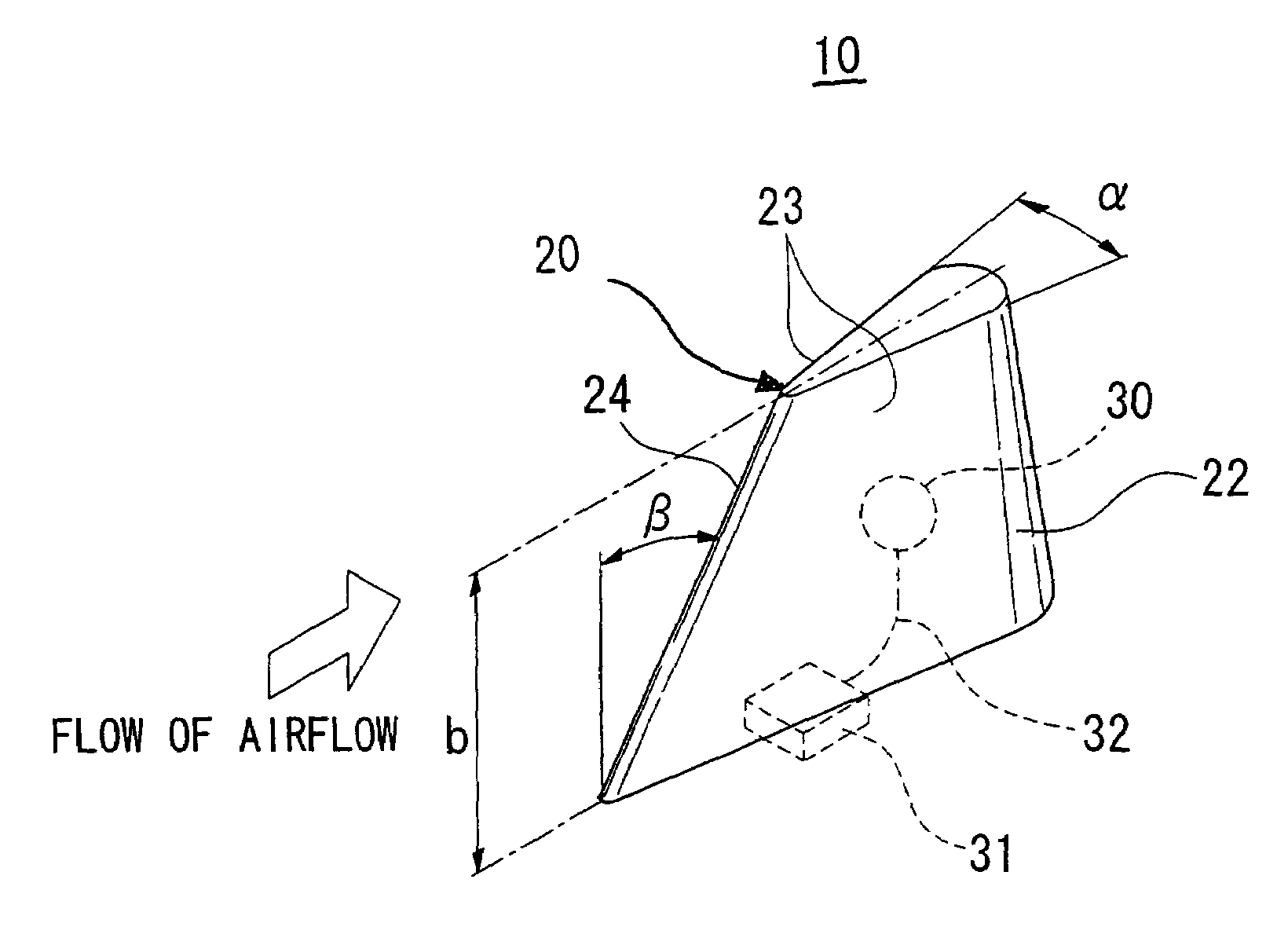
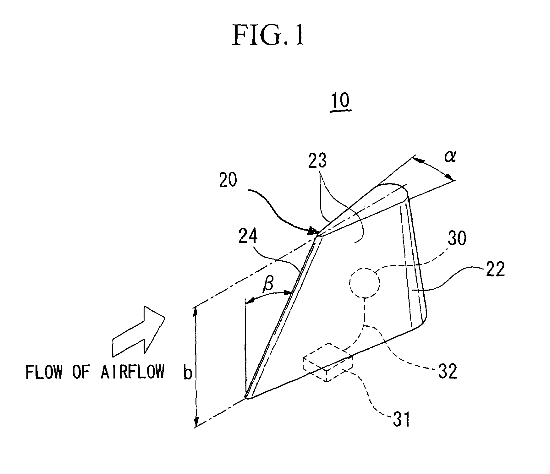
[0030]FIG. 1 is a perspective drawing showing an embodiment of the temperature measuring device of the present invention. This temperature measuring device 10 has a structure in which a temperature sensor 30 is built into a single wedge shaped casing 20 and the temperature measured by the temperature sensor 30 is transmitted to the exterior via an electric interface 31.

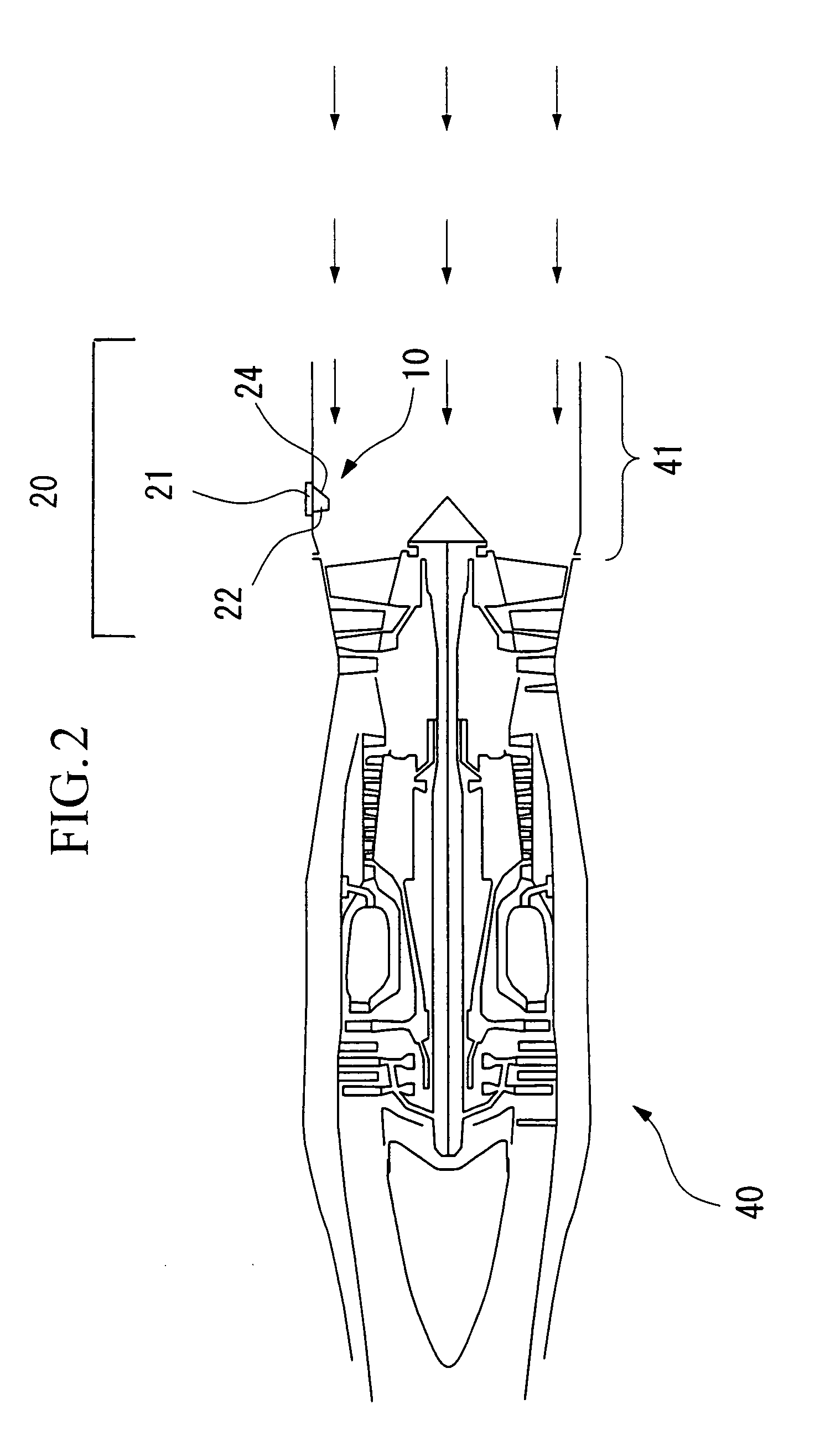
[0031]As shown in FIG. 2, casing 20 comprises a base 21 for the purpose of attaching the casing 20 to the airflow guide inlet 41 of the engine 40, and a sensor housing section 22. Sensor housing section 22 is formed so as to project from the base 21 into the airflow which is taken into the engine 40.

[0032]The sensor housing section 22 comprises two airflow traversing surfaces 23 which are arranged so that they are each at an angle of 9° with respect to the line of flow of the airflow and which together form a p...


PUM


Abstract

A temperature measuring device is provided which measures the total temperature T1 of an airflow based on the measured temperature T of the airflow flowing over the surface of an approximately blade-shaped casing arranged within the airflow flowing into an engine of the aircraft. The shape of the casing is set such that lumps of ice and snow, which may form on a surface of the casing and which may thereafter detach from the casing and strike the engine, detach at a stage of growth at which they do not cause damage to the engine.

Description

BACKGROUND OF THE INVENTION[0001]1. Field of the Invention[0002]The present invention relates to a temperature measuring device which is positioned within the airflow flowing into an engine of an aircraft or an external surface of the aircraft, and which measures the temperature of the airflow.[0003]2. Description of the Related Art[0004]Conventionally, on aircraft on which engines are mounted, temperature measuring devices which measure the temperature of airflows are arranged in the air intake or near the intake of the engines, or on an external surface of the aircraft.[0005]The air to the outside of a cruising aircraft forms an airflow at high speed, and it is necessary to measure the total temperature of this airflow. In order to measure the total temperature of the airflow, for example, a temperature measuring device having a structure in which the airflow is guided into a casing having a sensor located inside, a stagnation point in the airflow is formed by the airflow striking...

Claims


Application Information

Patent Timeline
IPC IPC(8): G01K1/08B64D15/00G01K1/14G01K13/02B64C23/00B64D43/00F02D35/00G01M9/06
CPCG01K13/028G01K13/02
Inventor SUGA, TARO
Owner YDK TECH CO
Why Eureka
Try Eureka