Hard tissue surface geometry determination

a hard tissue and surface geometry technology, applied in the direction of impression caps, instruments, applications, etc., can solve the problems of registration and/or other accuracy problems

Inactive Publication Date: 2006-03-21
TACTILE TECH
View PDF21 Cites 51 Cited by
  • Summary
  • Abstract
  • Description
  • Claims
  • Application Information

AI Technical Summary

Benefits of technology

[0027]In an exemplary embodiment of the invention, said tips include a bone stop which prevents entry of the elements into bone tissue past said a predetermined distance.

Problems solved by technology

The multiple position determination may cause registration and / or other accuracy problems.

Method used


Image

  • Hard tissue surface geometry determination
  • Hard tissue surface geometry determination
  • Hard tissue surface geometry determination

Examples


Embodiment Construction

Overview of Tooth Implant Problem

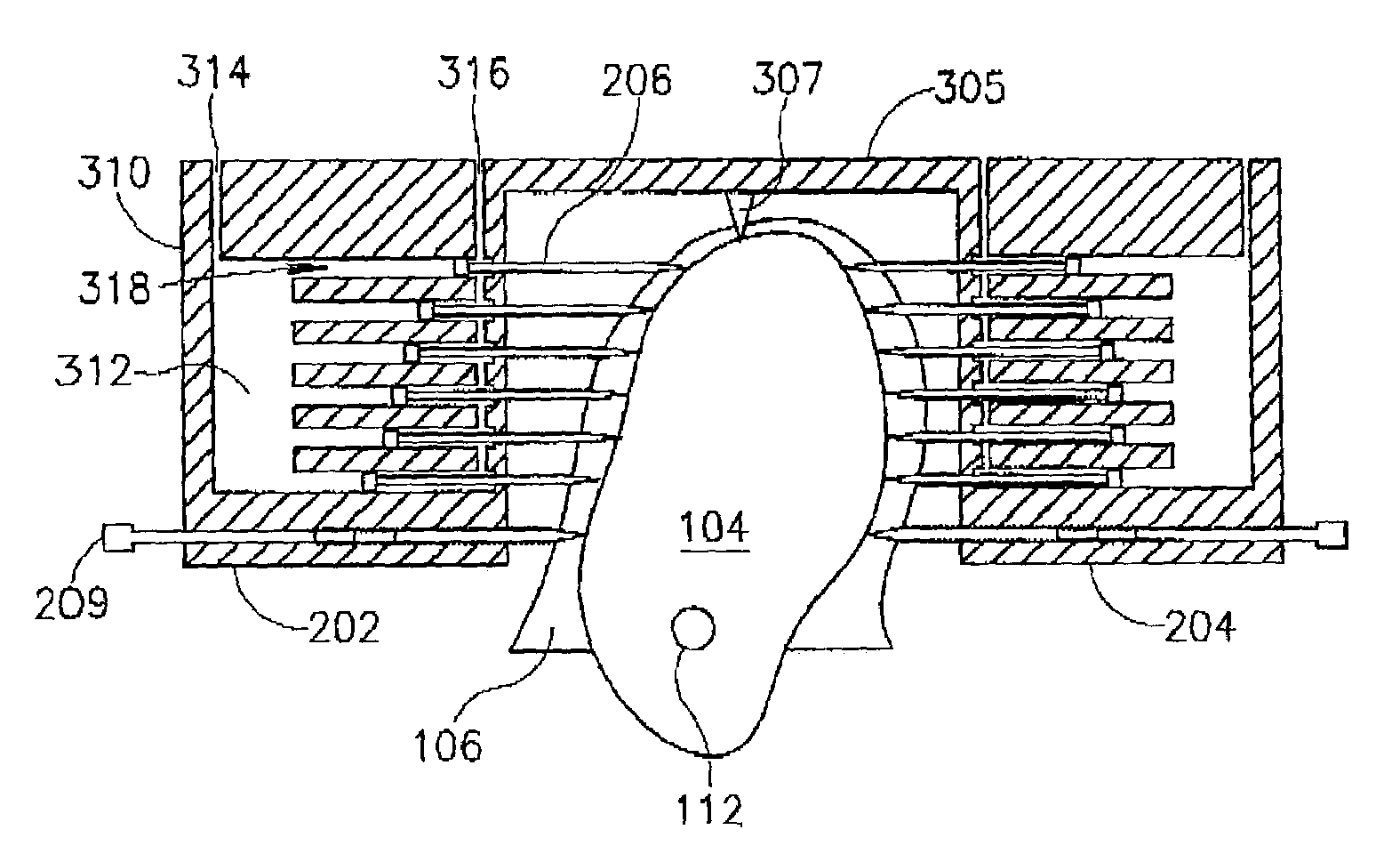
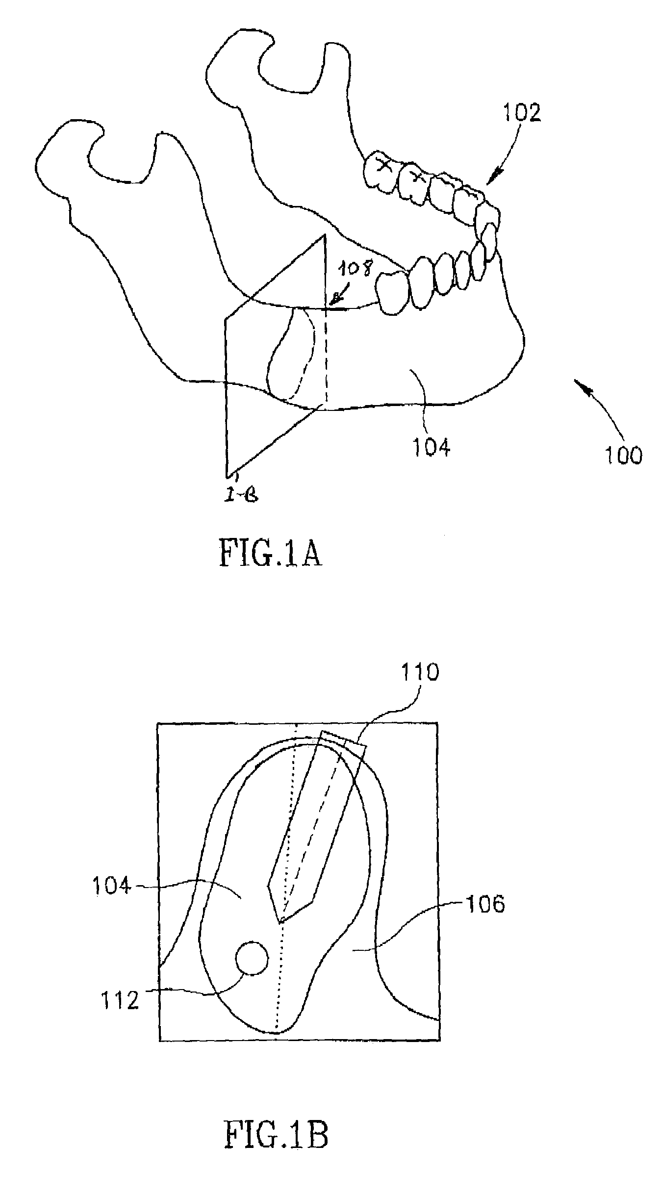
[0071]FIGS. lA and lB are a schematic isometric and a cross-sectional (along plane I-B of FIG. 1A) illustration of a jaw 100, showing the various layers thereof. A plurality of teeth 102 are embedded in a jaw-bone 104. A layer of soft gum tissue 106 overlays bone 104. If a tooth is missing, for example as in a space 108, the jaw bone may resorb, making later implantation difficult or impossible. In addition, there are esthetic considerations and a danger (if for example a bridge is not provided), that teeth might migrate into space 108. Thus, it is often desirable to implant new teeth instead of the missing teeth. While a tooth may be mounted using a bridge to nearby teeth, it may be desirable for a number of reasons that the tooth be anchored in jawbone 104. A typical procedure is to drill a bore 110 in jaw bone 104 and mount a tooth implant in bore 110. Two main dangers with the drilling are (a) the bore might be too close to the sides of jaw bone ...


PUM


Abstract

Apparatus for measuring a surface geometry of hard tissue covered by a layer of soft tissue, including a plurality of elements each having a tip adapted to penetrate said soft tissue and not substantially penetrate said hard tissue; a frame supporting movement of said elements, each along a path, such that a plurality of said tips, when positioned along the paths, define a surface; and at least one position sensor which generates a signal indicative of a tip position of at least one of said elements.

Description

FIELD OF THE INVENTION[0001]The present invention relates to the measurement of surface geometries, for example, of dental and bone tissues.BACKGROUND OF THE INVENTION[0002]There are many applications where knowing the surface structure or internal structure of hard tissue is desirable. A typical solution, especially if the hard tissue is underlying soft tissue as is the case in dental care, is to obtain X-Ray CT images of the hard tissue[0003]U.S. Pat. No. 5,562,448 to Mushabac, the disclosure of which is incorporated herein by reference, describes an array of sensors which are slid over one or more teeth, to determine its surface structure. However, the position of the array must be determined for each measurement of the array. This patent also describes a point-by-point digitizing of jaw-bone surface by penetrating overlying soft tissue to the bone with a sharp probe, multiple times, again, requiring position determination for each point digitization. The multiple position determ...

Claims


Application Information

Patent Timeline
Patent Type & Authority Patents(United States)
IPC IPC(8): A61C3/02A61B17/17A61B19/00A61C1/08A61C9/00A61C19/04
CPCA61B5/103A61C9/0046A61B5/4504A61B17/17A61B19/201A61B19/46A61C1/084A61C19/04A61B5/1077A61B17/176A61B19/54A61B2019/303A61B2019/461A61B2019/463A61B2019/5425A61B2019/5437A61B2562/046A61B5/6862A61B5/6878A61B5/407A61B2090/033A61B2090/063A61B90/11A61B90/06A61B2090/061A61B90/39A61B2090/3925A61B2090/3937A61B2562/17
Inventor WEINSTEIN, URIEL
Owner TACTILE TECH
Why Eureka
Try Eureka