Testing assembly and method for identifying network circuits

a network circuit and assembly technology, applied in the direction of testing/measuring connectors, network connectors, coupling device connections, etc., can solve the problems of difficult to distinguish and isolate the cable carrying the tone from all the other cables, process can take days or even weeks to complete, and the technician is more difficult to identify the tested wiring. , the effect of improving the speed and ease of identification

Inactive Publication Date: 2006-03-21
BELESIMO ADAM
View PDF15 Cites 46 Cited by
  • Summary
  • Abstract
  • Description
  • Claims
  • Application Information

AI Technical Summary

Benefits of technology

[0011]In accordance with the method of the present invention, one worker remains stationed at the patch panel location. A second worker applies a voltage, using the handset component of the present invention, to the plug in a remote location, which lights the corresponding LED on the patch panel, and only that LED. The worker at the patch panel communicates (usually by two-way radio) the information regarding the circuit that was illuminated to the worker at the remote location. Thus, the correct wire for that location on the patch panel is instantly identified, and can be labeled by the remote worker. The process in the present invention proceeds as fast as the remote worker can move from remote location to remote location. Furthermore, because of the ease with which the tested wiring can be identified, more than one worker can apply the tes

Problems solved by technology

This process can take days or even weeks to complete in large network cabling installations.
The difficulty that arises with this prior art method is that this process is quite time consuming and involves a great deal of trial and error.
Often this must be done in a small area that does not provide easy service access.
In addition, since these areas are generally small, the cables in question are quite close to one another making it more difficult for the technician to differentiate and isolate the cable carrying the tone from all of the

Method used


Image

  • Testing assembly and method for identifying network circuits
  • Testing assembly and method for identifying network circuits
  • Testing assembly and method for identifying network circuits

Examples


Embodiment Construction

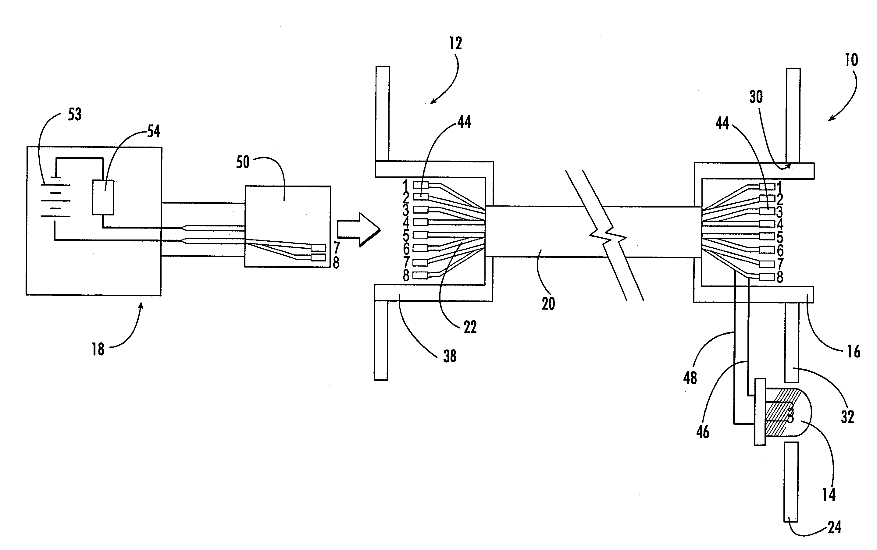
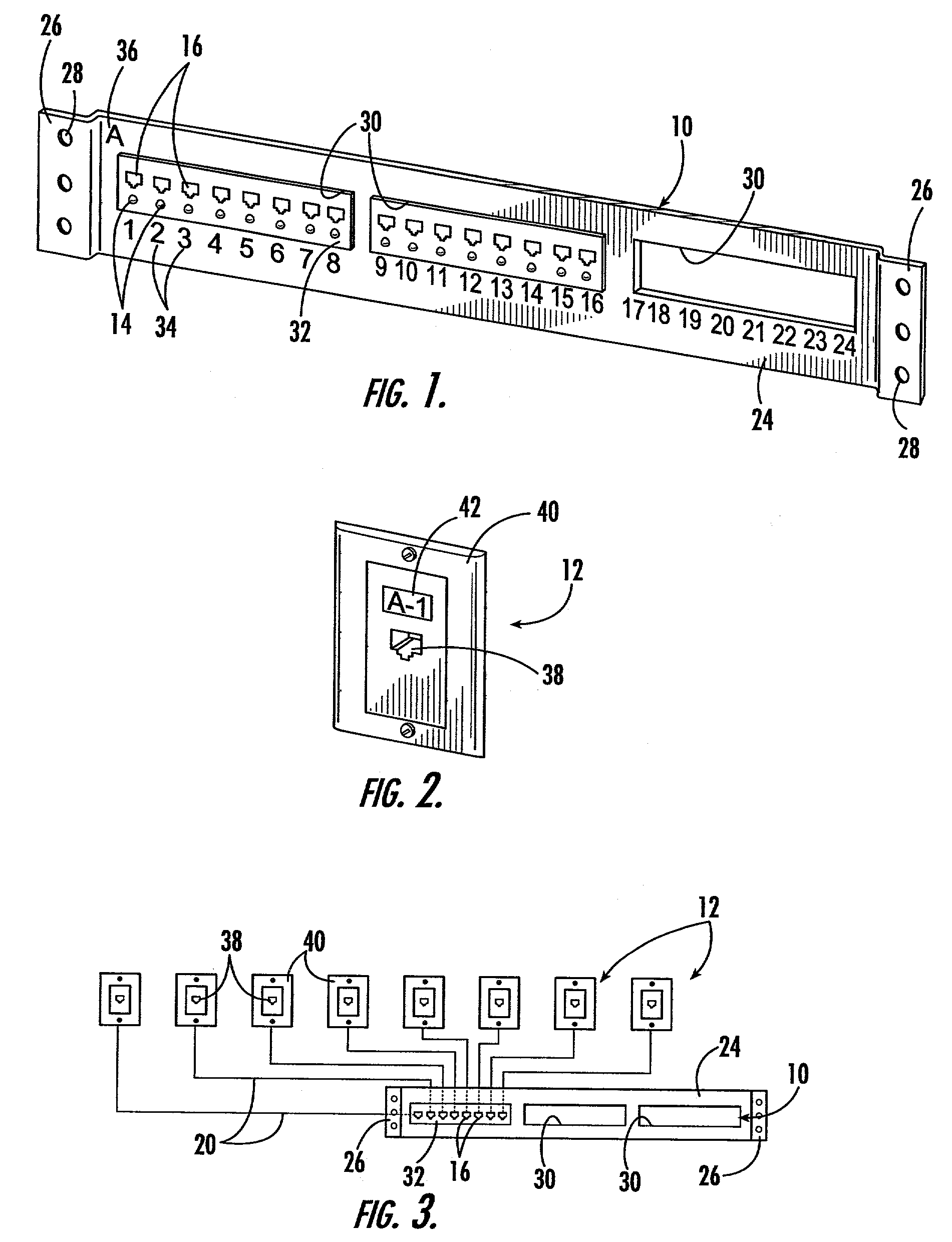
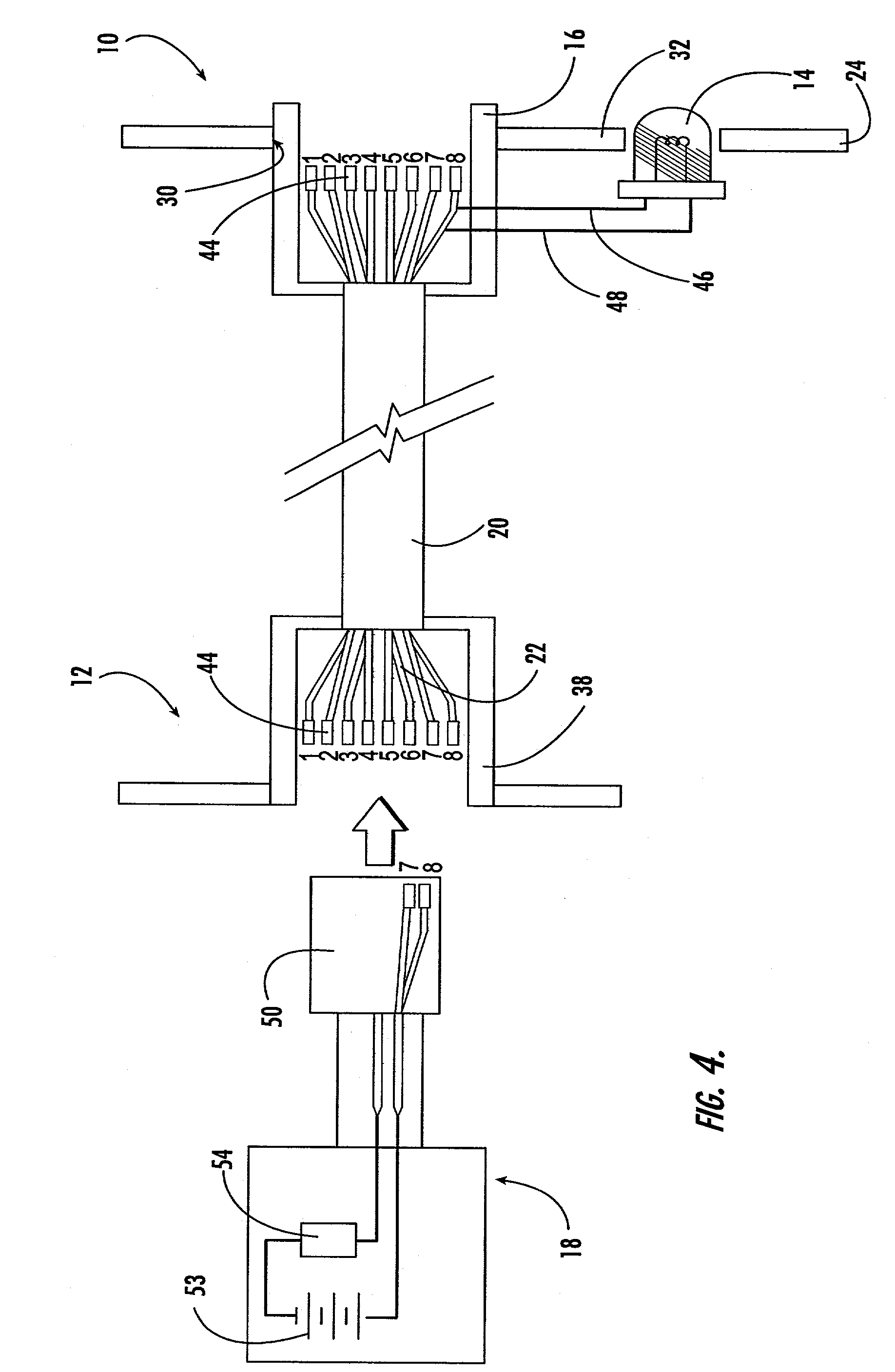
[0019]Referring now to the drawings, the cabling network testing apparatus of the present invention is illustrated in FIGS. 1–4. As will hereinafter be more fully described, the present invention includes testing apparatus for identifying particular cables in a cabling network that includes a network patch panel 10 and several remote wall jack 12 locations. The present invention provides for indicator lamps 14 that are installed in the patch panel device 10 adjacent to each of the patch jacks 16 installed therein to provide positive visual identification of the particular patch jack 16 that corresponds to the remote wall jack 12 location when a test voltage is applied at the remote location. As will be described, the apparatus and method of the present invention provide a simple cable identification system that can be operated more quickly and simply than the methods and apparatuses in the prior art.

[0020]The present invention generally includes two components, a patch panel compone...


PUM


Abstract

An improved method and apparatus for identifying individual wires that are connected between a network patch panel and a remote wall jacks is provided. A permanent LED lamp is installed adjacent to each jack in a computer network patch panel that is electrically connected to two terminals of each of the patch jacks. A handset component that produces direct current voltage is plugged into a remote wall jack to be tested, an electrical circuit is completed using the permanent network cabling thereby energizing the LED indicator lamp at the patch panel, providing positive visual confirmation of the patch panel location that corresponds to the wall jack location. The method of the present invention provides for one worker to remain at the patch panel location, as a second worker, using the handset component of the present invention, plugs the device into a wall plug in a remote location, which lights the corresponding LED on the patch panel. The worker at the patch panel communicates the circuit that was illuminated to the worker at the remote location. Thus, the correct wire for that location on the patch panel is instantly identified, and can be labeled by the remote worker.

Description

PRIORITY CLAIM TO PREVIOUSLY FILED APPLICATION[0001]This application claims priority to previously filed provisional patent application No. 60 / 329,728, filed Oct. 16, 2001.BACKGROUND OF THE INVENTION[0002]The present invention relates to a device and method for sorting and identifying electrical conductors, more particularly, the present invention relates to an improved method and apparatus for identifying individual wires or circuits from a plurality of wires or circuits extending between two remotely spaced locations.[0003]It is often necessary to identify individual wires or circuits that extend between two locations to match the two ends of the wire to one another. In the computer networking industry, a cable, typically containing four pairs of wires is used for each computer network connection between a distribution frame in a computer distribution location and the computer workstation. The distribution frame is typically called the “patch panel”, and it may contain hundreds, o...

Claims


Application Information

Patent Timeline
IPC IPC(8): H01R3/00H01R13/66H04Q1/14
CPCH01R13/6691H04Q1/20H04Q1/136H01R2201/04H01R2201/20
Inventor BELESIMO, ADAM
Owner BELESIMO ADAM
Why Eureka
Try Eureka