Electro-mechanical transmission systems

a transmission system and electromechanical technology, applied in the direction of differential gearings, belts/chains/gearings, toothed gearings, etc., can solve the problems of increasing the torque on the output shaft, unacceptably large, heavy and expensive, etc., and limiting the output torque available, so as to achieve the effect of increasing the torqu

Inactive Publication Date: 2006-03-21
NIDEC SR DRIVES
View PDF7 Cites 20 Cited by
  • Summary
  • Abstract
  • Description
  • Claims
  • Application Information

AI Technical Summary

Benefits of technology

[0014]According to one aspect, embodiments of the invention provide a method of increasing the torque applied to the output shaft of an electro-mechanical transmission system, particularly when accelerating from zero or low speed.
[0015]According to a first form of the invention there is provided an electro-mechanical transmission system, comprising at least two compounded epicyclic gearsets, one gear element of a first gearset being connected to an input shaft and one gear element of a second gearset being connected to an output shaft, the input shaft being connected to a prime mover, the rotors of two electric machines being connected to respective gear elements of the two gearsets, the electrical connections of the stators of which machines are connected together via a controller arranged to control the flow of electrical power between the machines and an energy receiver, the controller being operable to direct at least a proportion of electric power from that machine which is operating as a generator to the energy receiver. According to this form of the invention it is possible to increase the torque applied to the output shaft for a given prime mover and transmission system without having to modify the machinery. It has been found by the inventor that the torque increase is realized by dissipating some of the power from the prime mover instead of making it available as motive power, according to one example.
[0021]According to another aspect of the present invention there is provided a method of operating an electro-mechanical transmission system of the type comprising at least two compounded epicyclic gearsets, having an input shaft driven by a prime mover and connected to one gear element of a first gearset, an output shaft providing output torque and connected to one gear element of a second gearset, two electrical machines, the rotors of which are connected to respective gear elements of the two gearsets and each of which is able to operate either as a motor or a generator, a third electrical machine, operable as a motor, and having its output shaft connected to one of the input and output shafts of the transmission system, all three machines having the electrical connections of the stators of all three electrical machines being connected together via a controller arranged to control the flow of electrical power between the machines, which method includes increasing the torque available at the output shaft by directing electric power from at least one of the machines, for example that machine which is operating as a generator, to the third electrical machine.
[0025]Clearly, some method aspects of the invention will reduce the overall efficiency of the transmission system. A practical system might therefore avoid dumping energy except when large output torques are required, thereby only invoking aspects of the invention when needed to boost output torque. When aspects of the invention are used to boost torque, the diverted energy is used for some other auxiliary system or stored for later use, for example.
[0026]Thus, according to embodiments of the present invention, when, for example, a vehicle incorporating a transmission system of the type referred to is stationary and the vehicle engine is idling, the controller is set so that one of the electrical machines is generating only a small amount of electrical power and this power is transmitted to the other electrical machine. The sum of the torques at the two electrical machines is very small and only this very small torque acts on the output shaft. Movement of the vehicle is prevented by frictional losses and / or application of the vehicle brake.
[0030]Accordingly, with embodiments of the invention, the load is accelerated from rest more rapidly than was previously possible. Alternatively, for a given maximum rate of acceleration from rest, the two electrical machines are smaller, lighter and cheaper than was previously the case.

Problems solved by technology

The output torque available is limited by the ratings of the electrical machines.
This means either that the vehicle will accelerate relatively slowly or that the electrical machines must have relatively high ratings, in which event they will be unacceptably large, heavy and expensive.
This will increase the torque at that electrical machine and thus the torque on the output shaft.
However, this increase is not very large and can only be for a relatively short period of time unless both the battery and the electrical machines are of a size, which will make the transmission unacceptably heavy and expensive.
It is clear that one of the disadvantages of transmission systems of the type disclosed in WO-A-01 / 94142 is that they do not provide as much output torque as is sometimes desirable.

Method used


Image

  • Electro-mechanical transmission systems
  • Electro-mechanical transmission systems
  • Electro-mechanical transmission systems

Examples


Embodiment Construction

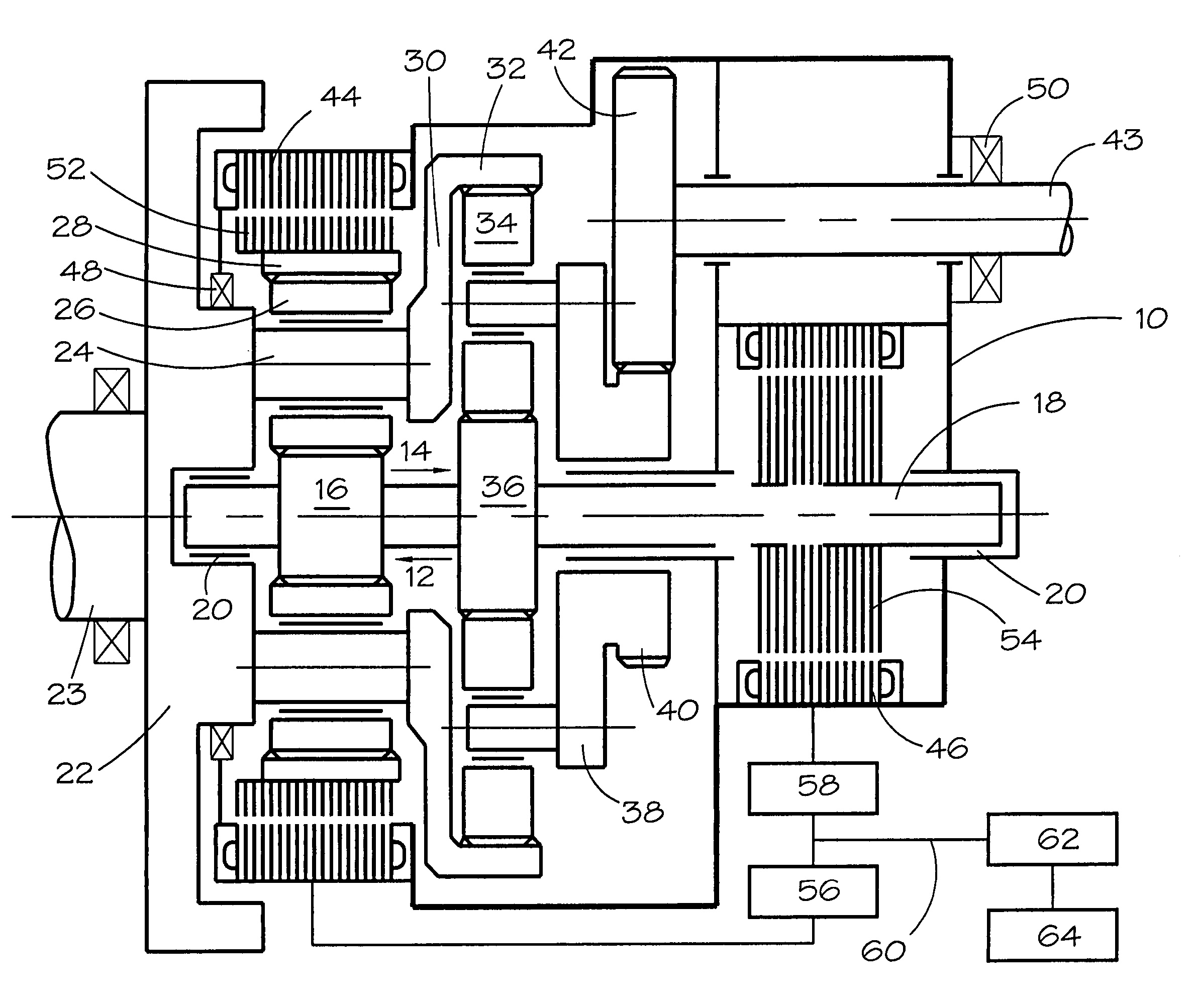
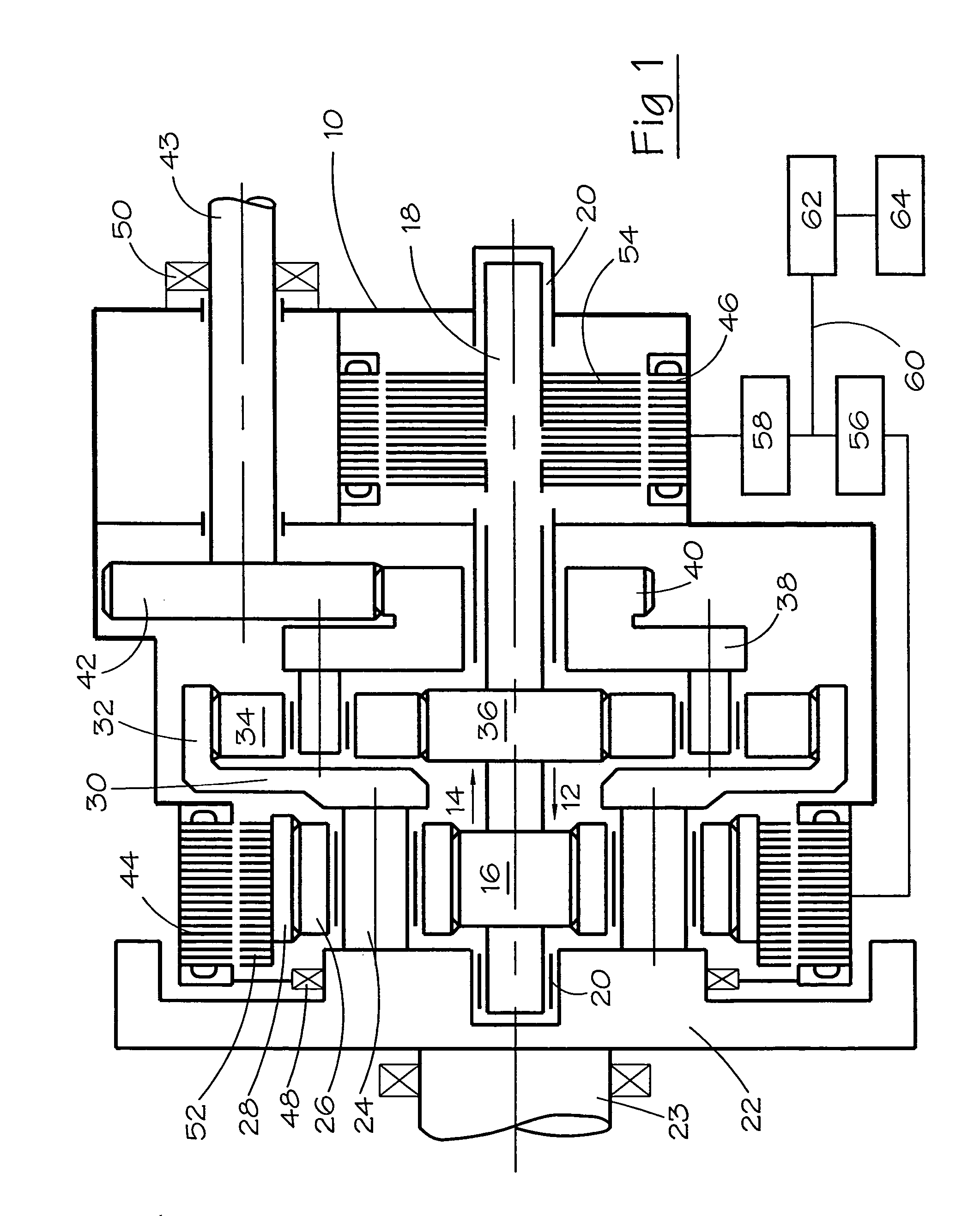
[0038]The transmission system shown in FIG. 1 comprises an outer housing 10 accommodating two epicyclic gearsets 12 and 14. The first gearset 12 comprises a first sun wheel 16, which is fixedly carried by a shaft 18, which is mounted to rotate with respect to the housing 10 by bearings 20. A first carrier 22, which constitutes a flywheel and is connected to an input shaft 23 carries a number (in this case three) of equispaced shafts 24, which carry respective first planet wheels 26. The first planet wheels 26 are in mesh with the first sun wheel 16 and with an internally toothed first annulus wheel 28.

[0039]The first carrier 22 is connected via a radial flange 30 to an annulus wheel 32 of the second gearset. The second annulus wheel 32 is in mesh with a plurality of second planet wheels 34 carried by a second carrier 38. The planet wheels 34 are also in mesh with a second sun wheel 36 fixedly carried by the shaft 18. The second carrier 38 includes an externally toothed portion 40, w...


PUM


Abstract

An electro-mechanical transmission system, driven by a prime mover, includes two epicyclic gearsets connected between input and output shafts, and two electrical machines having their rotors connected to respective elements of the two gearsets. The torque on the output shaft is boosted by a controller, which dumps energy from the system when one of the machines is acting as a generator and the other as a motor.

Description

CROSS-REFERENCE TO RELATED APPLICATION[0001]The subject matter of this application is related to the subject matter of British Patent Applications Nos. GB 0224714.6, filed Oct. 23, 2002 and GB 0229381.9, filed Dec. 17, 2002, priority to both of which is claimed under 35 U.S.C. § 119 and both of which are incorporated herein by reference.BACKGROUND OF THE INVENTION[0002]1. Field of the Invention[0003]The present invention relates to a method of operating electro-mechanical transmission systems.[0004]2. Description of Related Art[0005]A known form of electro-mechanical transmission system comprises two compounded epicyclic gearsets, having an input shaft driven by a prime mover and connected to one gear element of one gearset, an output shaft providing output torque and connected to one gear element of the other gearset, two electrical machines, the rotors of which are connected to respective gear elements of the two gearsets and each of which is able to operate either as a motor or a...

Claims


Application Information

Patent Timeline
Patent Type & Authority Patents(United States)
IPC IPC(8): F16H3/72B60K1/02B60K6/365B60K6/40B60K6/445B60W10/06B60W10/08B60W20/00
CPCB60K6/40B60K6/445B60W10/06B60W10/08B60W20/00F16H3/727B60K6/365B60K1/02Y10T477/24B60L2240/486B60W2710/105F16H2037/102F16H2037/104Y02T10/6286Y02T10/6239Y10T477/23Y02T10/62B60W30/18027B60W2050/0002B60W2710/08
Inventor RANDALL, STEVEN PAUL
Owner NIDEC SR DRIVES
Why Eureka
Try Eureka