Counting chamber provided with a reference and method for manufacturing a counting chamber provided with a reference

a technology of reference and counting chamber, which is applied in the field of counting chambers, can solve the problems of difficult realization of straight lines and thin lines by means of such a method, and achieve the effect of low cost manufacturing

Inactive Publication Date: 2006-03-21
VAN STRALEN J H W C +1
View PDF6 Cites 8 Cited by
  • Summary
  • Abstract
  • Description
  • Claims
  • Application Information

AI Technical Summary

Benefits of technology

[0009]Another object of the invention is to provide a counting chamber which meets the necessary quality requiremen

Problems solved by technology

A thin, straight line is difficult t

Method used


Image

  • Counting chamber provided with a reference and method for manufacturing a counting chamber provided with a reference
  • Counting chamber provided with a reference and method for manufacturing a counting chamber provided with a reference

Examples


Embodiment Construction

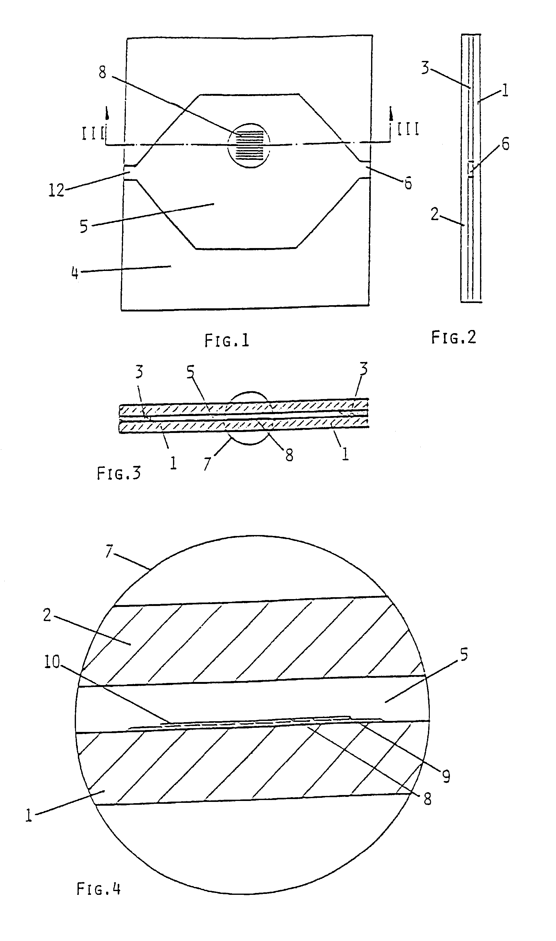
[0030]The figures show the embodiment only schematically, and for the sake of clarity the dimensions are not shown in their actual proportions in all cases.

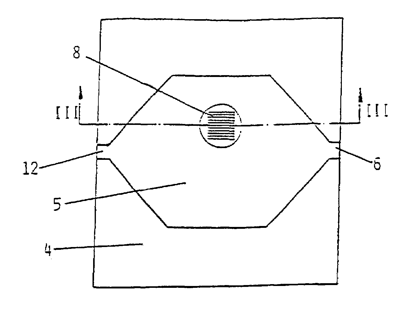
[0031]FIGS. 1 and 2 show in elevation the counting chamber consisting of two glass plates 1, 2, which are joined by film of glue 3. Said film of glue 3 does not cover the entire area between the glass plates 1, 2, but only the area 4 in FIG. 1, which surrounds an area that forms chamber 5.

[0032]Film of glue 3 has a specific thickness, in order to space the glass plates 1, 2 a specific, constant distance apart. Said specific thickness of the film of glue 3 can be achieved by putting spherical particles into the glue, for example glass spheres having a diameter equal to the desired distance between glass plates 1, 2.

[0033]Chamber 5 is enclosed by the two glass plates 1, 2 and the film of glue 3, therefore. It is possible to gain access to chamber 5 from the outside via openings 6, 12. Chamber 5 can be filled through one of said ope...


PUM


Abstract

Disclosed is a counting chamber for optical detection of particles that are present in a fluid, comprising two substantially transparent and substantially parallel plates of material, between which the fluid can be introduced. At least one of the plates includes a visible reference, which comprises a relief formed on the surface of the plate.

Description

BACKGROUND OF THE INVENTION[0001]1. Field of the Invention[0002]The invention relates to a counting chamber for optical detection of particles that are present in a fluid, comprising two substantially transparent and substantially parallel plates of material, between which the fluid can be introduced, wherein at least one of said plates includes a visible reference.[0003]2. Description of the Related Art[0004]Such counting chambers can be used for examining blood, urine or sperm and all other fluids.[0005]The term reference is understood to means a visible image, in particular an image which visibly delimits parts of the counting chamber when a person is viewing the counting chamber through a microscope. The particles that are present in the fluid can be quantified in that case by counting or estimating the number of particles that are present in a specific delimited section.[0006]The reference can also be a gauge, which is divided into units of length, so that it is possible to det...

Claims


Application Information

Patent Timeline
IPC IPC(8): G01N1/10G01N15/10G02B21/34
CPCG02B21/34G01N2015/1062
Inventor DE KOCK, ALFONS PETRUS ANTONIUS GERRITVAN STRALEN, JOANNES HENDRICUS WILHELMUS CORNELISWESTENDORP, HENDRIK JANWESTERVELD, CORNE ARJEN
Owner VAN STRALEN J H W C
Why Eureka
Try Eureka