Micro-optic fiber device

a technology of micro-optic fiber and optical fiber, which is applied in the direction of optics, instruments, optical light guides, etc., can solve the problems of high thermal dependence loss and insertion loss of devices, low acceptance rate of final products, and difficult finding of skilled workers

Inactive Publication Date: 2006-03-21
LIGHTEL TECH
View PDF4 Cites 4 Cited by
  • Summary
  • Abstract
  • Description
  • Claims
  • Application Information

AI Technical Summary

Benefits of technology

[0011]The primary object of the present invention is to provide a micro-optic fiber device, wherein the optical processing elements, micro lenses and the fiber pigtails can be coupled by virtue of independent counter-bore tubes and coupling tubes, such that the micro-optic fiber device can be built by coupling the counter-bore tubes and the coupling tubes, thus eliminating the need of using bonding agent between the optical processing element and then micro lenses and preventing the bonding agent from diffusing and spreading over the optical path of the optical processing element as well as the micro lenses.

Problems solved by technology

The acceptance rate of the final products is accordingly low and skilled workers are not easy to find.
Stresses need to be applied on the elements for aligning purposes in the case of soldering, therefore the devices built suffer from high thermal dependent loss and insertion loss.
This step, to some extent, has become the bottleneck in manufacturing the micro-optic fiber device.
Although simple, the approach does not provide devices with optimal reflection and transmission insertion loss.

Method used


Image

  • Micro-optic fiber device
  • Micro-optic fiber device
  • Micro-optic fiber device

Examples


Embodiment Construction

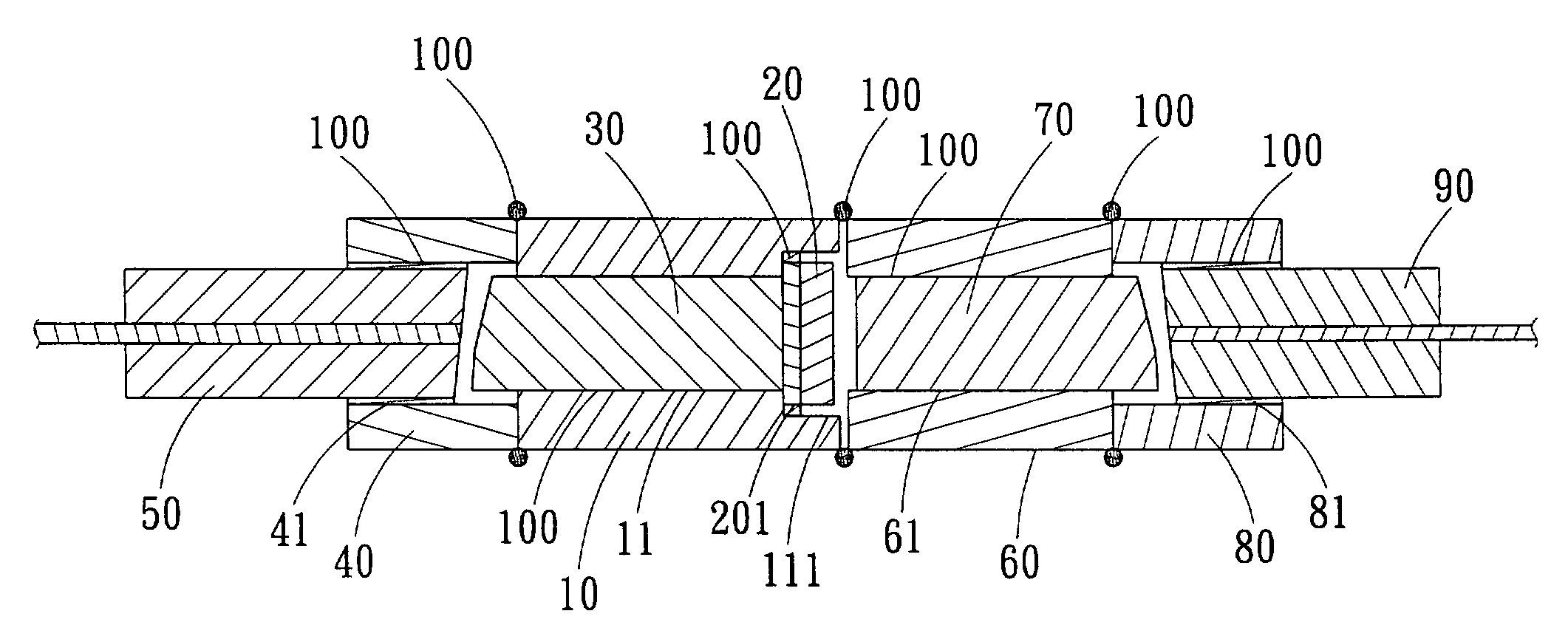
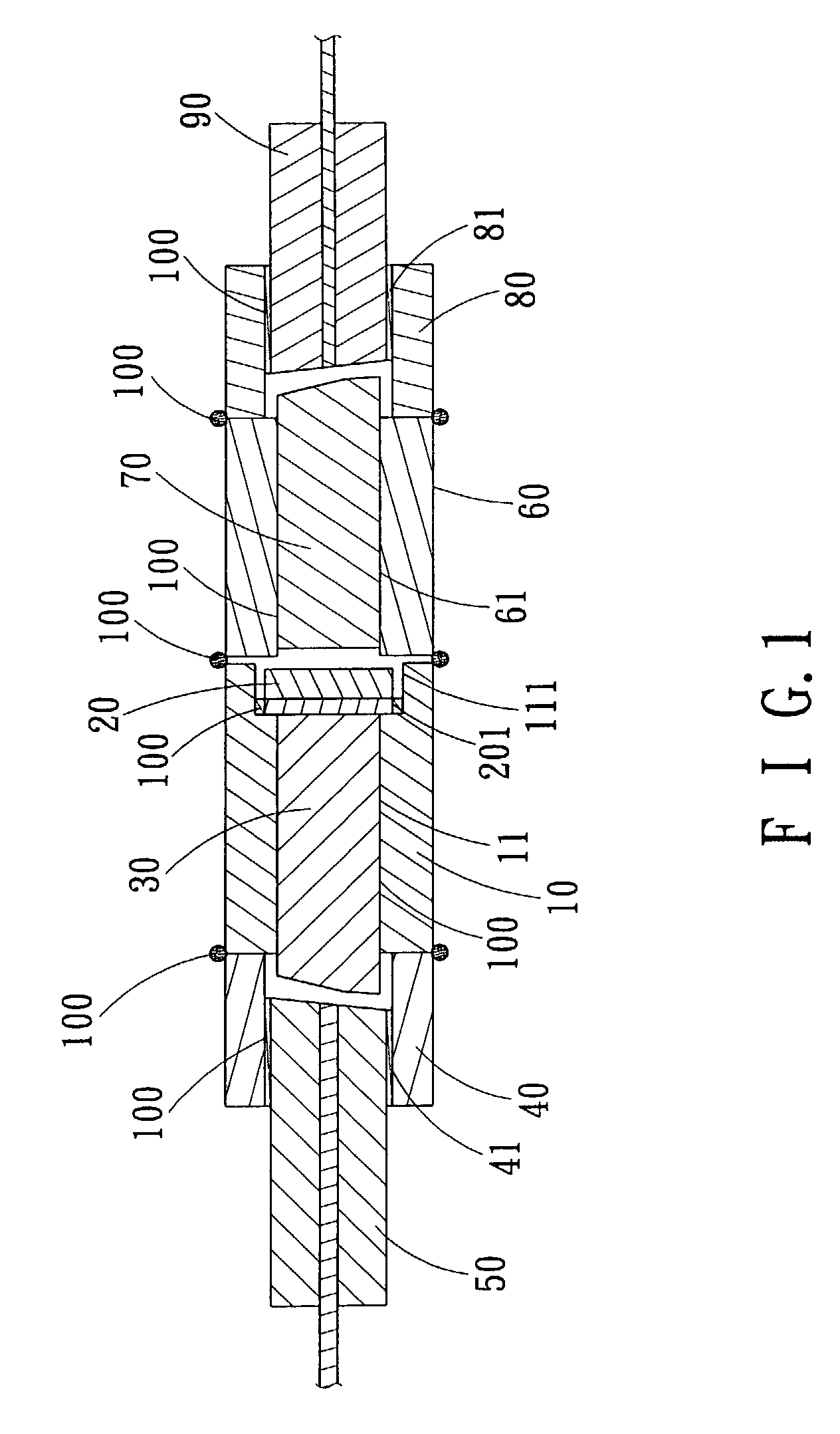
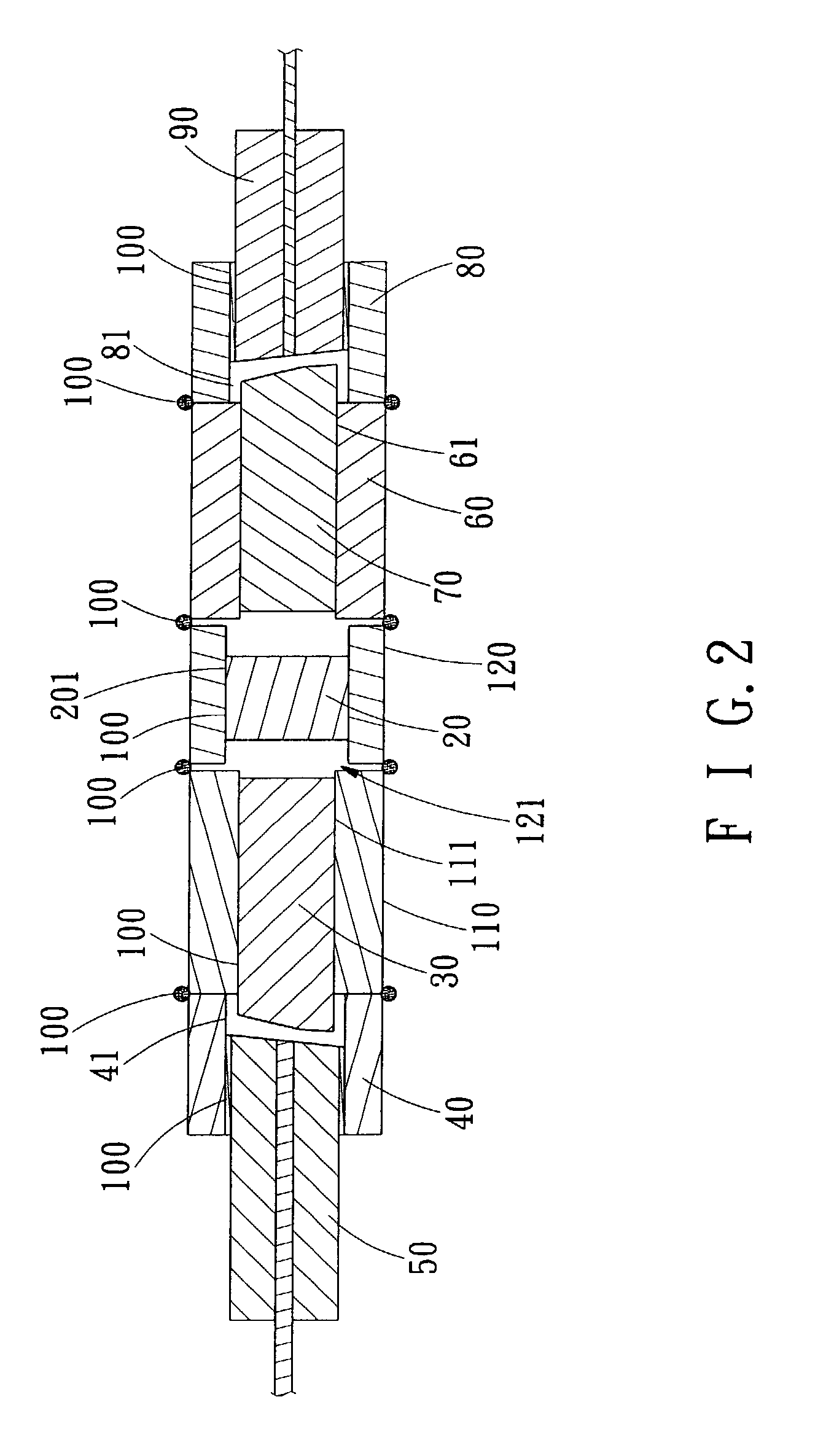
[0019]Referring to FIG. 1, wherein a micro-optic fiber device is shown and generally comprising: an optical processing element 20 here taking wavelength division multiplexed (WDM) device as an example), a counter-bore tube 10, three coupling tubes 40, 60, 80, a pair of micro lenses 30, 70 (such as GRIN lenses), a dual fiber pigtail 50 and a single fiber pigtail 90.

[0020]The counter-bore tube 10 interiorly defines a through passage 11. At an end of the passage 11, a step groove 111, which has a greater diameter than the passage 11, is defined for insertion of the optical processing element 20. The epoxy or solder 100 is applied to the outer periphery 201 of the optical processing element 20 and the inner surface of the step groove 111 for strengthening the bonding between the counter-bore tube 10 and the optical processing element 20. The first micro lens 30 is likewise fixed in the passage 11 of the counter-bore tube 10 using epoxy or solder 100 to form a subassembly (including the ...


PUM


Abstract

A micro-optic fiber device is provided with independent counter-bore tubes and coupling tubes serving as couplers for coupling the optical processing elements, micro lenses and the fiber pigtails. The micro-optic fiber device can be built using direct coupling manner, wherein the optical processing element is firstly inserted and fixed in the step groove of the counter-bore tube by applying bonding agent between the outer periphery of the optical processing element and the inner surface of the step groove, and then the counter-bore tube is coupled with the coupling tubes, thus eliminating the need of using bonding agent between the optical processing element and the micro lenses and preventing the bonding agent from diffusing and spreading over the optical path.

Description

BACKGROUND OF THE INVENTION[0001]1. Field of the Invention[0002]The invention relates to a micro-optic fiber device, and more particularly to the technology for coupling, disposing and slightly turning the respective component such as the optical processing element, the fiber collimators, and the coupling tubes, which constitute the micro-optic fiber device.[0003]2. Description of the Prior Arts[0004]The most popular approach to making a micro-optic fiber device is to make two fiber collimators separately and insert an optical processing element such as WDM filters, isolator cores, birefringent crystals of PM combiners, and circulator cores in between to form fiber optic WDM devices, fiber-in-line-isolators, fiber PM combiners, and fiber circulators respectively. In the conventional art the collimators are attached to the optical processing elements either using soldering (tin solder) or bonding (epoxy). Usually the outer housing of the above-mentioned collimators is made of metals,...

Claims


Application Information

Patent Timeline
Patent Type & Authority Patents(United States)
IPC IPC(8): G02B6/32G02B6/26
CPCG02B6/264G02B6/32
Inventor HSIA, CHUNG-HOSHEN, PAI-SHENG
Owner LIGHTEL TECH
Why Eureka
Try Eureka