
Inventory management system for reducing overall warehouse and pipeline inventory

Inactive Publication Date: 2006-03-21
UNITED PARCEL SERVICE OF AMERICAN INC
View PDF44 Cites 25 Cited by
  • Summary
  • Abstract
  • Description
  • Claims
  • Application Information

AI Technical Summary

Benefits of technology

The present invention provides an improved logistics system for tracking and managing parts in a central warehouse. The system allows for reallocation of parts from one entity to another without physically moving them, and keeps a record of all the parts in the warehouse. The system also allows for the assignment of different identification indicia to parts, and provides a history of all the parts in the warehouse. The system can also include value-added services, such as labeling or assembly of parts, and can be used in a network of manufacturing facilities. Overall, the invention provides a more efficient and effective way of managing parts in a central warehouse.

Problems solved by technology

Of course, due to the realities of the manufacturing and logistics worlds, such an idealized situation would be difficult, if not impossible, to achieve.
The unpredictability typically associated with shipping parts over long distances has also made it difficult to attain the idealized logistics situation described above.
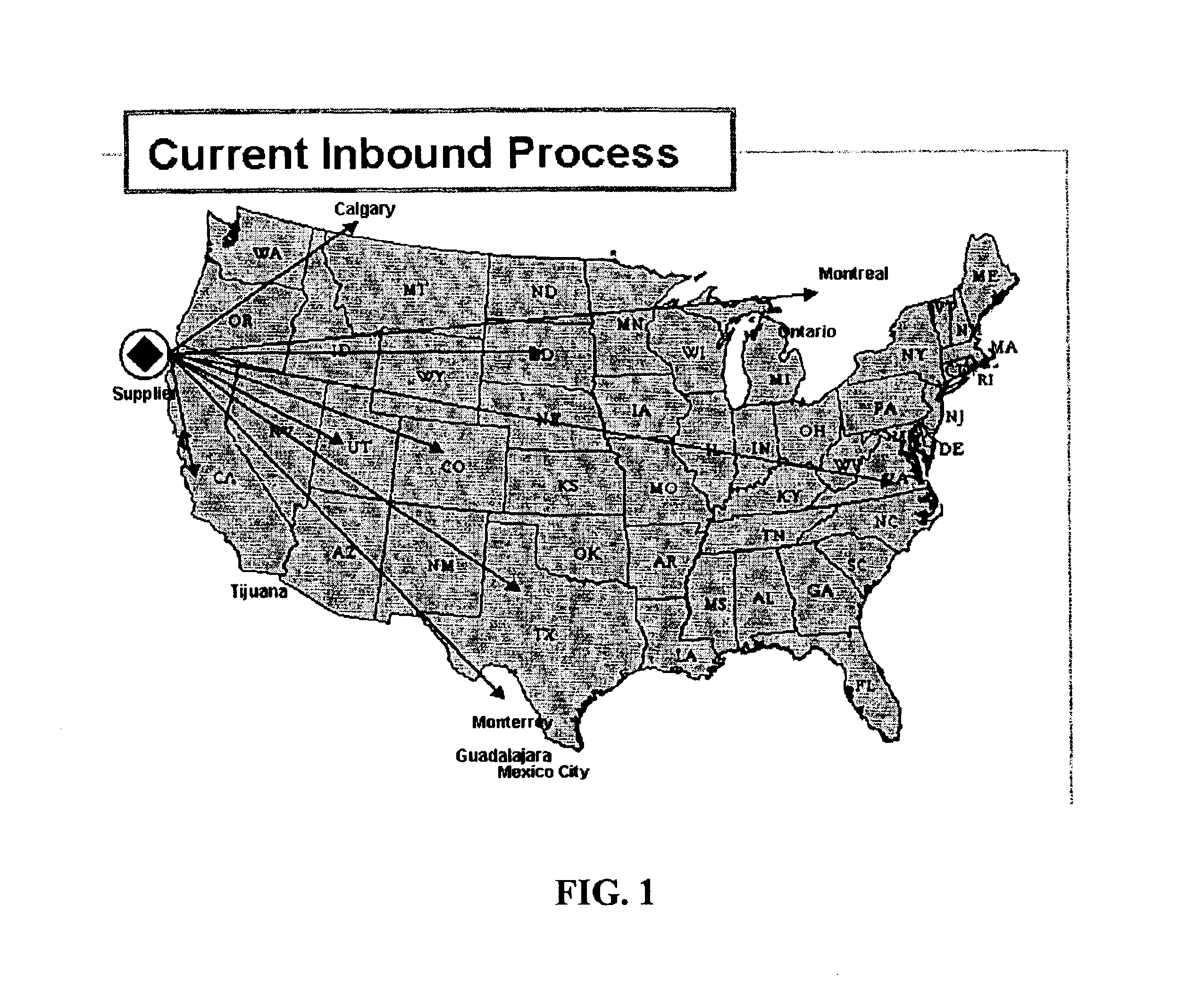
These real-world uncertainties have resulted in unpredictable supply streams in which it is difficult to determine exactly when parts will arrive at a given manufacturing plant (or at a local storage facility, such as a proximity hub, associated with the manufacturing plant).
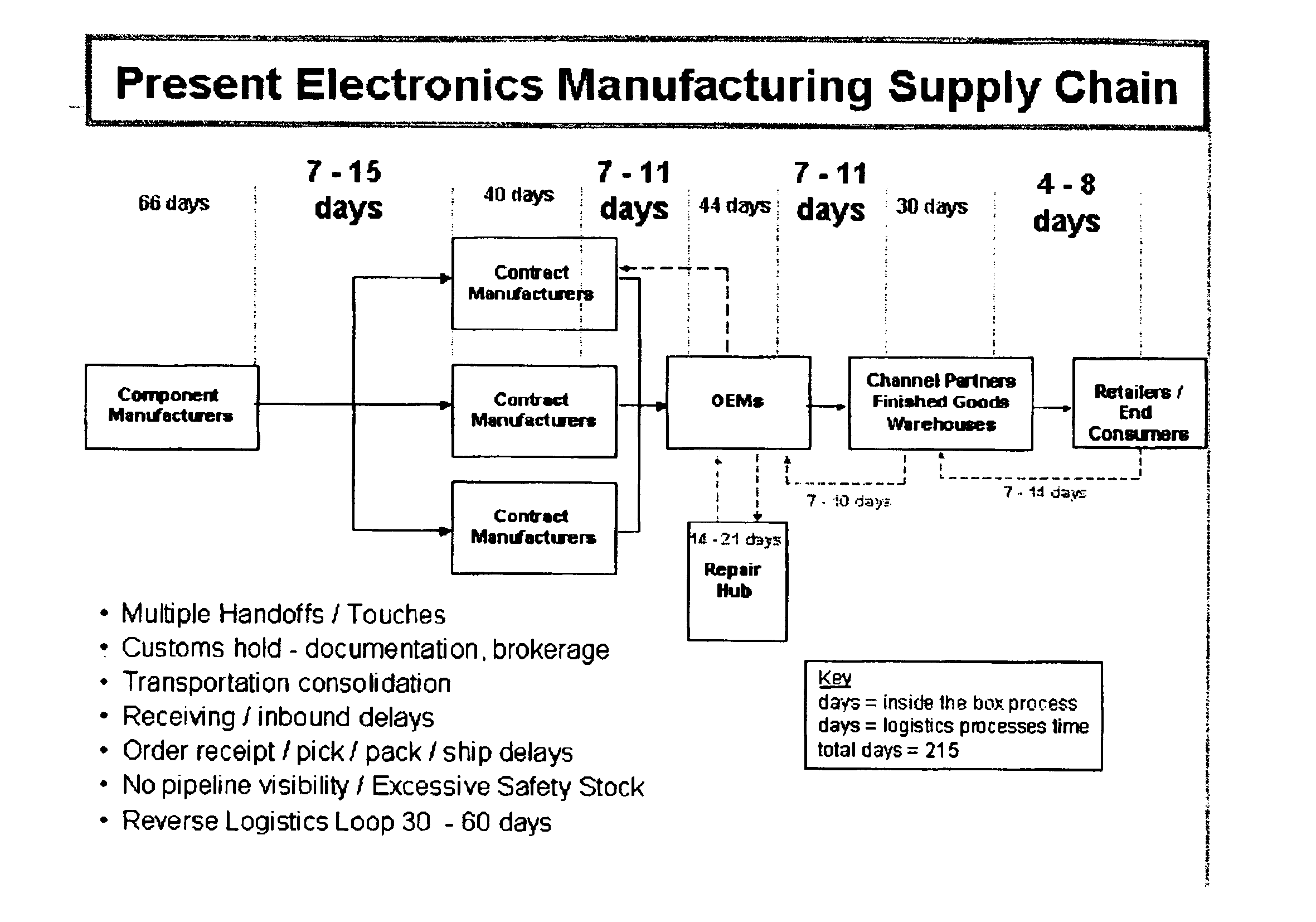
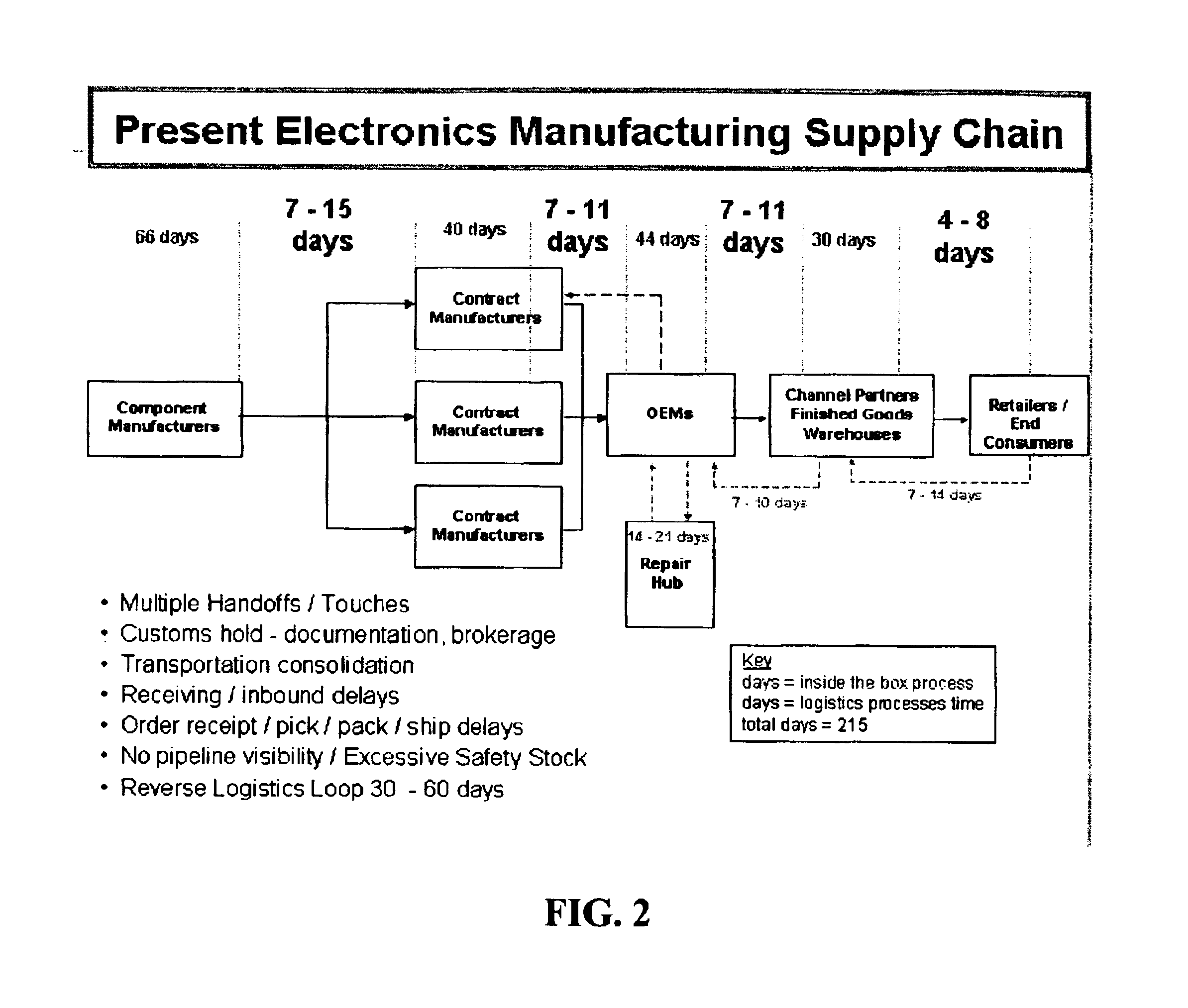
However, if the manufacturer can only rely on needed parts to arrive within a seven day delivery window, the manufacturer would need to keep a significantly larger safety stock on hand to assure uninterrupted operation of the manufacturing facilities.
In recent years, demand for electronic components has been relatively low.
This forces the suppliers to bear the cost and risk of maintaining the manufacturer's safety stock (and of maintaining this inventory on their books), and to dedicate an often unnecessarily excessive amount of stock to a single manufacturing facility.
Understandably, because current VMI practices are unfavorable to suppliers, very few suppliers are willing to agree to such arrangements.
In addition, it is expected that, as demand for component parts increases, even fewer (if any) suppliers will be willing to agree to these prior art VMI arrangements.
One particular disadvantage of current VMI systems is lack of visibility.
As a result, suppliers have difficulty obtaining information on the status and allocation of their parts while the parts are stored at the proximity hubs, and manufacturers have difficulty obtaining information regarding their current allocation of parts and the shipping status of these parts.
As will be understood by one skilled in the relevant filed, this, along with unpredictable variations in demand, has contributed to the undesirable “bullwhip effect”, which causes manufacturers to request that excessive numbers of parts be maintained at their proximity hubs.
This lack of visibility has also made it difficult for suppliers to quickly and effectively re-allocate parts from one manufacturer to another in response to changing market conditions.
The following is a list of selected disadvantages associated with current VMI arrangements:1. They result in an excessive amount of inventory being stored at the various proximity hubs.
Thus, manufacturers monopolize the inventory, but have no commitment to buy it.
Furthermore, manufacturers often over-order to make absolutely sure that they will always have the components that they need.
Thus, this situation is not advantageous for the supplier.2. Revenue realization is delayed for the supplier because ownership of the supplier's goods is not transferred until the goods are “pulled” for use by the manufacturer.3. The supplier's inventory is fragmented into multiple proximity hubs that are typically run by multiple (small) 3PL organizations.
This increases the risk that certain parts may go unused.4. There is typically no unified inventory visibility once parts are consigned to proximity hubs.5. It is difficult, using prior art VMI systems, to reallocate consigned inventory based on changes in demand.6. The demand fragmentation at a large number of proximity hubs reduces forecast accuracy.7. It is difficult and expensive to aggregate parts using current VMI systems.8. The overall visibility available according to current, prior art VMI arrangements is typically very low.
As a result, even if a supplier had extra parts at one proximity hub, and needed parts at another proximity hub, the supplier would have no way of knowing this.9. The lack of visibility within current VMI systems leads to a lack of trust by the manufacturers that their parts will arrive on time.
This is a further incentive for manufacturers to order more parts from the supplier than they really need, which results in unnecessarily high inventory costs.10.
Because large stockpiles of safety stock are maintained at the VMI, suppliers are exposed to the risk that the stored products will become obsolete while in storage.
This is a significant risk in industries, such as the electronics industry, in which parts tend to become outdated quickly.

Method used


Image

  • Inventory management system for reducing overall warehouse and pipeline inventory
  • Inventory management system for reducing overall warehouse and pipeline inventory
  • Inventory management system for reducing overall warehouse and pipeline inventory

Examples


Embodiment Construction

[0044]The present invention now will be described more fully hereinafter with reference to the accompanying drawings, in which preferred embodiments of the invention are shown. This invention may, however, be embodied in many different forms and should not be construed as limited to the embodiments set forth herein. Rather, these embodiments are provided so that this disclosure will be thorough and complete, and will fully convey the scope of the invention to those skilled in the art. Like numbers refer to like elements throughout.

[0045]As will be appreciated by one skilled in the art, the present invention may be embodied as a method, a data processing system, or a computer program product. Accordingly, the present invention may take the form of an entirely hardware embodiment, an entirely software embodiment or an embodiment combining software and hardware aspects. For example, the present invention may be embodied in a computer system that is configured to coordinate, preferably ...


PUM


Abstract

A computer system for use in reducing overall pipeline inventory within a distribution network that includes a central warehouse that is: (1) adjacent a transportation hub; and (2) configured to store sufficient component parts to provide a regular stream of parts to each of a plurality of manufacturing facilities. The computer system is preferably configured for coordinating the transportation of a regular stream of parts to each of the manufacturing facilities by transporting component parts from the central warehouse to the manufacturing facilities primarily via an expedited delivery service performed using the transportation hub. The expedited delivery service may include, for example, guaranteed delivery within one or two days. This reduces the overall pipeline and warehouse inventory within the distribution network by reducing the average transit time for each part, and by reducing the amount of safety stock that is needed to support the operations of the manufacturing facilities.

Description

CROSS REFERENCE TO RELATED APPLICATION[0001]This application claims the benefit of U.S. Provisional Application Ser. No. 60 / 363,604, which was filed on Mar. 11, 2002, and which is hereby incorporated herein by reference.FIELD OF THE INVENTION[0002]This invention relates to systems and methods for coordinating the delivery of items (such as component parts) from a supplier to a manufacturer. This system and method is discussed below in relation to delivering component parts from a supplier of electronics components (or “parts”) to an electronics manufacturer. However, as will be understood by one skilled in the art, the concepts described below may be applied to coordinating the delivery of other items, such as mechanical parts or finished consumer items.BACKGROUND OF THE INVENTION[0003]One important aspect of manufacturing is maintaining a reliable and predictable supply chain of components from suppliers to manufacturers. A typical supply chain requires the involvement and coordina...

Claims


Application Information

Patent Timeline
Patent Type & Authority Patents(United States)
IPC IPC(8): G06F7/00G06F19/00B65G61/00G06Q10/00
CPCG06Q10/087G06Q10/08
Inventor PENKAR, RAJAN C.JOHNSON, MICHAEL D.HANLON, LARRY A.REULBACH, RAYMOND A.JONES, GINA L.CASTAGNO, TONY R.
Owner UNITED PARCEL SERVICE OF AMERICAN INC
Learn More